Fixing An Elgato Cam Link’s USB Current Draw Issue

Recently [Bits und Bolts] found himself in a bit of a pickle, when on boot his PC would complain about a connected USB device drawing too much power, before shutting down again. After unplugging various USB devices, the problem was narrowed down to an Elgato Cam Link 4K video capture device.

Some prodding and poking around with a thermal camera on the disassembled device while powered showed that an onboard IC had sprung a power leak. Sadly, even asking nicely, Elgato support wasn’t going to provide board-level repair help, so this was left as an exercise to the owner.

Although the markings on the chip didn’t offer much help, it turns out that this is a more common issue, with a convenient repair guide by [Uldis Melderis] identifying the part as the TI TLV62585 buck regulator.

After purchasing a couple of spares, the defective IC could then be replaced. Following this a quick test showing decidedly less angry electrons. From there it was a matter of reassembling the device in its plastic case and seeing whether the PC was happier with the now hopefully fixed device, which fortunately turned out to be the case.

Any such analysis and repair obviously raises a number of questions, such as why these buck regulators are dying, and why you’re supposed to just toss out a $100 device instead of doing a repair involving a $0.20 part and a few minutes with a hot air gun.
DIY Reflow Plate Runs On USB Power Delivery

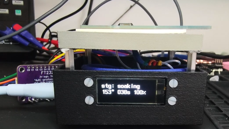
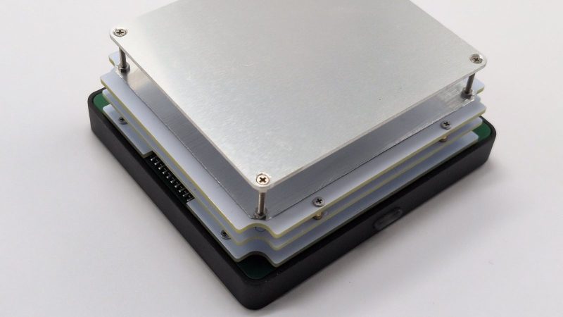
If you’re working with surface mount components, you’re likely going to want a reflow plate at some point. [Vitaly] was in need of just such a tool, and thus whipped up a compact reflow plate that is conveniently powered via USB-C. 

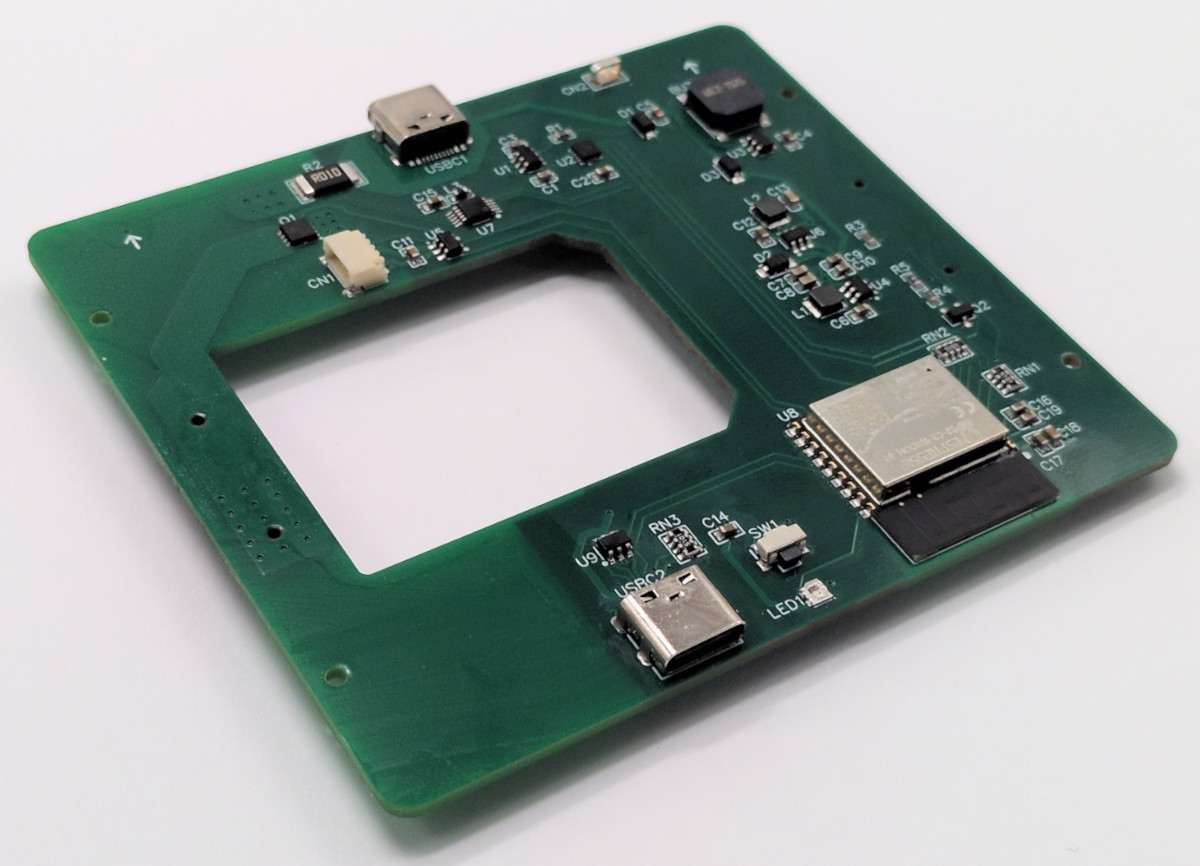
This reflow rig is designed for smaller work, with a working area of 80 mm x 70 mm. There are two options for the heating element—either a metal core PCB-based heater, or a metal ceramic heater. The former is good for working with Sn42Bi58 solder paste at 138 C, according to [Vitaly], while the latter will happily handle Sn63Pb37 at 183 C if the dirty stuff is more your jam.

Running the show is an ESP32-C3-WROOM, which serves up a web-based control panel over Bluetooth for setting the heating profiles. Using Bluetooth over WiFi might seem like an odd choice at first, but it means you don’t have to add the hot plate to the local wireless network to access it, handy if you’re on the move. It’s also worth noting that you can’t run this off any old USB charger—you’ll need one compatible with USB Power Delivery (PD) that can deliver at least 100 watts.

If you’re needing to whip up small boards with regularity, a hotplate like this one can really come in handy. Files are on GitHub for those eager to build their own.

This isn’t the first time we’ve seen USB-C powering a small reflow plate. Of course, if you make your PCBs self heating, you can sidestep all that entirely.

USB-C Powered Hotplate Is Not For Food

Once upon a time, it was deemed mostly silly to try and schlep power from a computer’s ports. Then it was kind of amusing to do so with USB, and before you knew it, we were running whole laptops off what started out as a data connector. These days, it’s not unusual to run a soldering iron off USB-C, or, as [MarkTheQuasiEngineer] has done—a hotplate!

This hotplate is not for quesadillas, nor samosas. Instead, it’s a tiny hotplate for tiny reflow tasks. Given many PCBs are quite small, there’s no need for a huge hot plate to get your circuits assembled.

The device relies on metal ceramic heating elements to provide the warmth. An NTC thermistor is used for monitoring the temperature for accurate control, which is handled by the STM32 microcontroller that’s running the show. It also drives a small display indicating the mode of operation and current temperature. The STM32 controls the power going to the heating element from the USB-C feed with a stout power MOSFET.

Sadly, the project hasn’t been a complete success. With a PCB on the plate, [MarkTheQuasiEngineer] was only able to achieve peak temperatures of around 200 C. That’s not great for doing proper reflow, but it’s a start. He believes upgrading to a more powerful supply to feed the hotplate will help.

We’ve featured some other great reflow hotplates before too.
Continue reading “USB-C Powered Hotplate Is Not For Food”

A Compact SMD Reflow Hotplate Powered By USB-PD

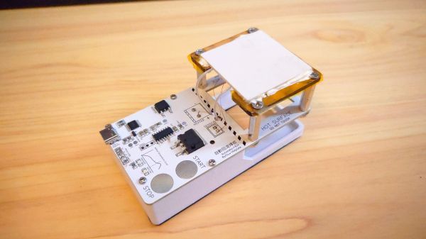
When it comes to home-lab reflow work, there are a lot of ways to get the job done. The easiest thing to do perhaps is to slap a PID controller on an old toaster oven and call it a day. But if your bench space is limited, you might want to put this compact reflow hotplate to work for you.

There are a lot of nice features in [Toby Chui]’s build, not least of which is the heating element. Many DIY reflow hotplates use a PCB heater, where long, thin traces in the board are used as resistive heating elements. This seems like a great idea, but as [Toby] explains in the project video below, even high-temperature FR4 substrate isn’t rated for the kinds of temperatures needed for some reflow profiles. His search for alternatives led him to metal ceramic heaters (MCH), which are commonly found in medical and laboratory applications. The MCH he chose was rated for 20 VDC at 50 watts — perfect for powering with USB-PD.

The heater sits above the main PCB on a Kapton-wrapped MDF frame with a thermistor to close the loop. While it’s not the biggest work surface we’ve seen, it’s a good size for small projects. The microcontroller is a CH552, which we’ve talked about before; aside from that and the IP2721 PD trigger chip needed to get the full 60 watts out of the USB-PD supply, there’s not much else on the main board.

This looks like a nice design, and [Toby] has made all the design files available if you’d like to give it a crack. Of course, you might want to freshen up on USB-PD before diving in, in which case we recommend [Arya]’s USB-PD primer.

Continue reading “A Compact SMD Reflow Hotplate Powered By USB-PD”

Solder Two Boards At Once With This Dual Reflow Plate

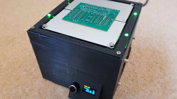
Homebrew reflow projects generally follow a pretty simple formula: find a thrift shop toaster oven or hot plate, add a microcontroller and a means to turn the heating element on and off, and close the loop with a thermistor. Add a little code and you’re melting solder paste. Sometimes, though, a ground-up design works better, like this scalable reflow plate with all the bells and whistles.

Now, we don’t mean to hate on the many great reflow projects we’ve seen, of course. But [Michael Benn]’s build is pretty slick. The business end uses 400-watt positive temperature coefficient (PTC) heating elements from Amazon controlled by solid-state relays, although we have to note that we couldn’t find the equivalent parts on the Amazon US site, so that might be a problem. [Michael] also included mechanical temperature cutoffs for each plate, an essential safety feature in case of thermal runaway. The plates are mounted at the top of a 3D-printed case, which also has an angled enclosure for a two-color OLED display and a rotary encoder.

The software runs on an ESP32 and supports multiple temperature profiles for different solder pastes. The software also supports different profiles on the two plates, and even allows for physical expansion to a maximum of four heating plates, or even just a single plate if that’s what you need. The video below shows it going through its paces along with the final results. There’s also a video showing the internals if that’s more your style

We appreciate the fit and finish here, as well as the attention to safety. Can’t find those heating elements for your build? You might have to lose your appetite for waffles.

Continue reading “Solder Two Boards At Once With This Dual Reflow Plate”

Tour A PCB Assembly Line From Your Armchair

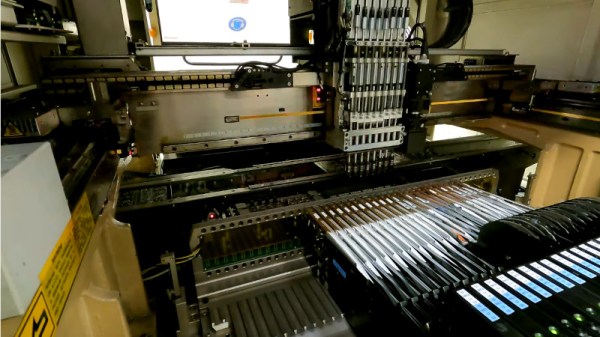
Those of us who build our own electronics should have some idea of the process used to assemble modern surface-mount printed circuit boards. Whether we hand-solder, apply paste with a syringe, use a hotplate, or go the whole hog with stencil and oven, the process of putting components on boards and soldering them is fairly straightforward. It’s the same in an industrial setting, though perhaps fewer of us will have seen an industrial pick-and-place line in action. [Martina] looks at just such a line for us, giving a very accessible introduction to the machines and how they are used. Have a look, in the video below the break.

It’s particularly interesting as someone used to the home-made versions of these machines, to see the optical self-alignment and the multiple pick-and-place tools which are beyond the simpler pick-and-place machines you’ll find in a hackerspace. Multiple machines in a line are also beyond hackerspaces, so the revelation that the first machine is deliberately run slowly to avoid the line backing up is a valuable one.

At the end of the line is the reflow oven itself, through which the boards pass on a belt through carefully graded hot air zones. Certainly a step up from a toaster oven with an Arduino controller!

Sadly not all of us will be lucky enough to have such a line at our disposal, but pick-and-place projects come up here quite often. We did a teardown on the feeders from a Siemens machine a couple of years ago.

Continue reading “Tour A PCB Assembly Line From Your Armchair”

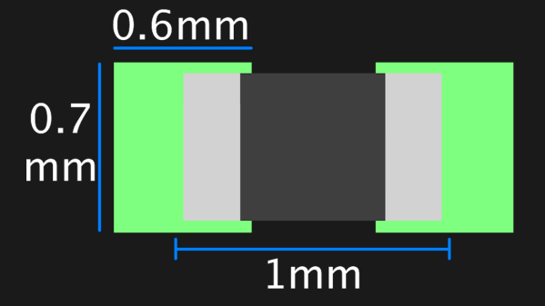
A graphic showing the suggested footprint dimensions for 0402 parts

Want Better 0402 Reflow? Consider These Footprints!

Assembling with a stencil is just that much more convenient – it’s a huge timesaver, and your components no longer need to be individually touched with a soldering iron for as many times as they have pads. Plus, it usually goes silky smooth, the process is a joy to witness, and the PCB looks fantastic afterwards! However, sometimes components won’t magically snap into place, and each mis-aligned resistor on a freshly assembled board means extra time spent reflowing the component manually, as well as potential for silent failures later on. In an effort to get the overall failure rate down, you will find yourself tweaking seemingly insignificant parameters, and [Worthington Assembly] proposes that you reconsider your 0402 and 0201 footprints.

Over the years, they noticed a difference in failure rates between resistor&capacitor footprints on various boards coming in for assembly – the size and positioning of the footprint pads turned out to be quite significant in reducing failure rate, even on a tenth of millimeter scale. Eagle CAD default footprints in particular were a problem, while a particular kind of footprint never gave them grief – and that’s the one they recommend we use. Seeing the blog post become popular, they decided to share their observations on 0201 as well, and a footprint recommendation too. Are your 0402 resistors giving you grief? Perhaps, checking the footprints you’re using is a good first step.

The 0402 and 0201 components are in a weird spot, where soldering iron assembly is no longer really viable, but the stencil+reflow approach might not be unilaterally successful when you start off – fortunately, that’s where writeups like these come in. Interested in learning stenciling? Get some solder paste, and read up on all the different ways you can put it onto your boards.