As hackers and makers we are surrounded by accessible computing in an astonishing diversity. From tiny microcontrollers to multi-processor powerhouses, they have become the universal tool of our art. If you consider their architecture though you come to a surprising realisation. It is rare these days to interface directly to a microprocessor bus. Microcontrollers and systems-on-chip have all the functions that were once separate peripherals integrated into their packages, and though larger machines such as your laptop or server have their processor bus exposed you will never touch them as they head into your motherboard’s chipset.
A few decades ago this was definitely not the case. A typical 8-bit microprocessor of the 1970s had an 8-bit data bus, a 16-bit address bus, and a couple of request lines to indicate whether it wanted to talk to memory or an I/O port. Every peripheral you connected to it had to have some logic to decode its address and select it when you wanted to use it, and all shared the processor’s bus. This was how those of us whose first computers were the 8-bit machines of the late 1970s and early 1980s learned the craft of computer hardware, and in a world of Arduino and Raspberry Pi this now seems a lost art.
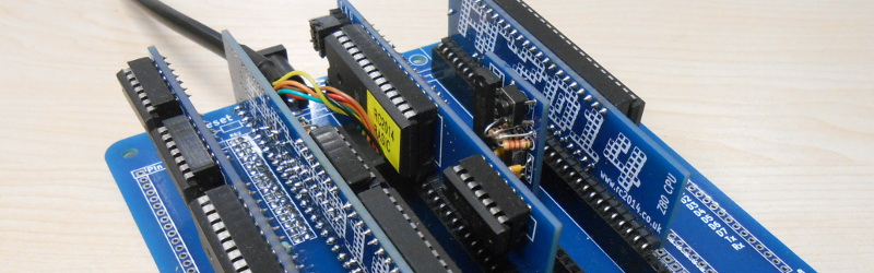
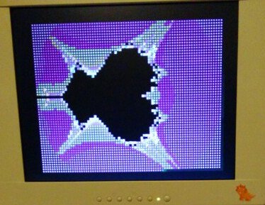
The subject of today’s review then provides a rare opportunity for the curious hardware hacker to get to grips with a traditional microprocessor bus. The RC2014 is a modular 8-bit computer in which daughter cards containing RAM, ROM, serial interface, clock, and Z80 processor are ranged on a backplane board, allowing complete understanding of and access to the workings of each part of the system. It comes with a ROM BASIC, and interfaces to a host computer through a serial port. There is also an ever-expanding range of further peripheral cards, including ones for digital I/O, LED matrixes, blinkenlights, a Raspberry Pi Zero for use as a VDU, and a small keyboard.
The Build
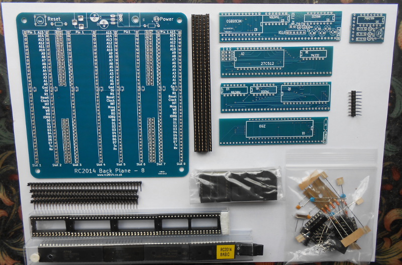
Opening the packaging, the components and boards are neatly packed in plastic bags. There was no printed documentation with our kit (Update 2016-09-09 – Our kit was supplied a few months ago, the designer tells us in the comments that the kits now come with printed instructions.), instead all documentation can be found on the project web site. The components are all easily identifiable, with through-hole passive components, sockets for the ICs, and large dual-in-line chips with clear markings. The modular nature of the kit means that each of the daughter cards has relatively few components, meaning that it splits the work into conveniently-sized units that are easy to build.
The exception to this convenience comes with the backplane, upon which are placed a series of long single-in-line sockets. It’s easy enough to solder 0.1″ pitch devices like these, but mildly tedious given the number of pins to be soldered. The outer two sockets have their data and address lines isolated by a set of jumpers which aren’t supplied, you will need to find and strip some hook-up wire to make these connections.
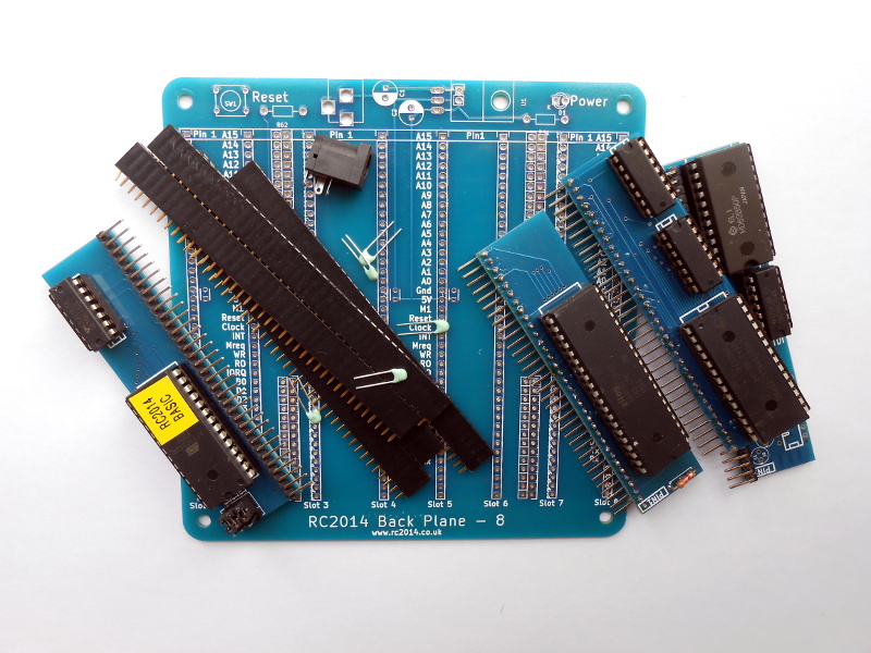
Part of the daughter board assembly is the attachment of a row of right-angle pins to mate with the backplane sockets. At this point during the assembly or our review system a flaw became obvious in the build. Different RC2014 daughter boards face in different directions, and by mistake we put the pins on the wrong side of a couple of the boards. It’s not an insurmountable problem but it slightly limits the order in which our modules can be placed. We’d suggest a very careful study of the online manual and photographs for each board, and not to be lulled into a false sense of security by the project’s relative ease of construction.
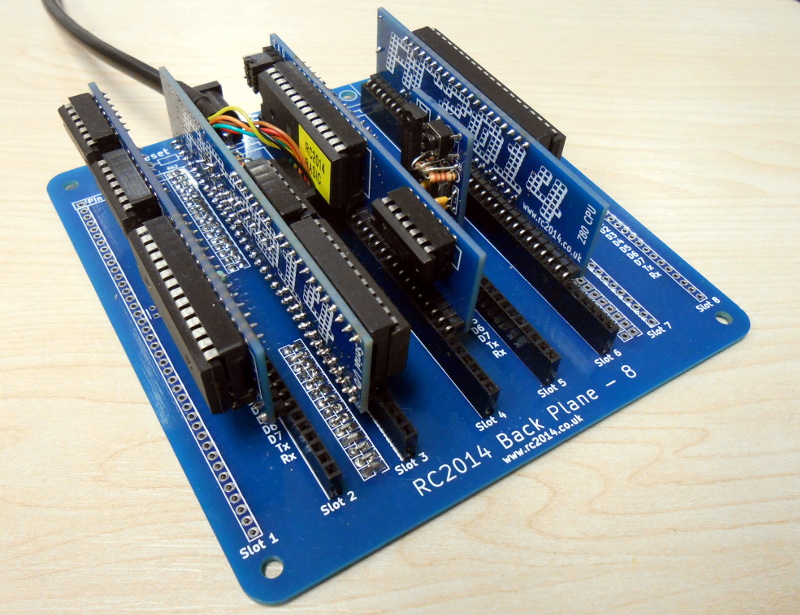
When all your daughter boards are ready it is a simple procedure to place them on the backplane. Pin 1 is clearly indicated on each board and can easily be aligned with the corresponding socket position. The only non-full-length board in the set is the clock oscillator, this is easily aligned not with pin 1 but with the GND pin marked on the backplane.
The build of our system was marred by the temperature controller on the soldering iron failing and the bit reaching a red-hot temperature. At the time this led to a Hackaday article on Weller tip availability, but for our RC2014 build it meant that on completion our system did not work. It exhibited a strange almost-functionality in which text sent from the RC2014 to the host computer could be read, but that sent from host to RC2014 was garbage.
With a lot of fault-finding with an oscilloscope, support from the kit’s designer, and continuity testing of connections failing to find an answer the kit languished until August’s EMF Camp, at which point it was possible to meet him face-to-face to get to the bottom of the problem once and for all. After an hour’s heroic customer support sitting amid the barbecue fumes of a festival hackspace village we finally traced the problem to an intermittent fault in one of the sockets. The extra-high soldering temperature had weakened a contact spring leaving it as a high enough resistance to cause problems but not enough to be detected as an open circuit. A quick replacement delivered instant results, and we had a working RC2014.
Up and Running
The build completed and a description of the hardware behind us, how about the software? Using the RC2014 could not be simpler, given an FTDI serial to USB lead you simply plug it into your host computer, configure the serial settings of your terminal software, press the reset button and away you go. The RC2014 is not an energy-hungry device, so happily takes its power via the FTDI from a USB slot.
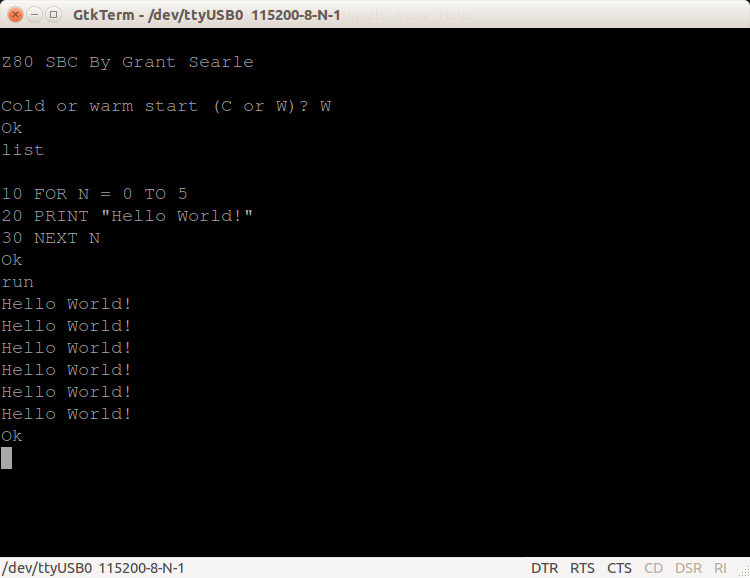
The ROM BASIC comes courtesy of [Grant Searle], and is derived from one used in the Nascom computer kits of the late 1970s. It has a full implementation of a typical BASIC of the era, along with some custom keywords for conversion to binary and hex values. On start-up it gives you the option of using the existing memory contents if it has been reset, followed by that of specifying a custom memory limit. Those choices over, and you find yourself in a BASIC interpreter; ready to dredge up those half-forgotten tricks gleaned from hours of typing in listings as a teenager.
Happily many contemporary BASIC programs written for similar computers can be ported to the RC2014, and there is a GitHub repository with a lot of the hardware and ROM info as well as some BASIC examples. Loading code into the RC2014 without tediously typing can be done if your terminal supports sending text files to the serial port.
In a world in which we expect instantaneous computing it comes as something of a shock to run some software on the RC2014 and realise that it can take quite a while to complete. A BASIC interpreter on a few-MHz 8-bit microprocessor is hardly fast by today’s standards. But buyers of the RC2014 are after the 8-bit experience rather than the computing power it offers, so in that sense it offers an authentic peek into the past. Users of machines like this decades ago would have considered them to be startlingly quick, and minutes for a complex calculation would have seemed inconsequential compared to the hours required to do the same task by hand.
Do you Need One?
The RC2014 is probably the best way to get to grips with typical 8-bit microcomputer hardware of the era around 1980 that is available to the enthusiast some 35 years later. The modular design and clearly labelled bus probably make it more suitable for the experimenter than the single board designs of the day, when fault-finding the review board it was extremely easy to identify and trace signals with an oscilloscope. We certainly came away from this build knowing the machine at a much lower level than we would have with something more integrated.
If there is a gripe though with the RC2014 though it lies in its lack of physical documentation (Update 2016-09-09 – Our kit was supplied a few months ago, the designer tells us in the comments that the kits now come with printed instructions.). Our experience with the faulty soldering iron was sheer bad luck, but we might have avoided the other minor wrong turnings we made had the information been more easily digested. This is however a minor issue as everything is there online if you are prepared to take it in and the support we received was of a very high quality, we would simply recommend to a would-be RC2014 builder that they take the time to really familiarise themselves with all the available information.
The RC2014 has full hardware information available on its website, and can be bought as a kit and with its ever-expanding range of peripheral boards through Tindie. If you have an interest in retro 8-bit microcomputer architectures then we can heartily recommend you take a look at it.


This will be my biggest competitor once my L-Star project goes into production (https://hackaday.io/project/3620). It’ll be the old 6502 vs Z80 wars from the 1980s all over again muwahahaha!
(Just kidding, I really like this project and I’m thinking of buying one and maybe making a 6502 version, I contacted the maker, Spencer Owen and I think he likes the idea).
Yes, I love the idea of a 6502 variant. One RC2014 owner has already done that though; http://danceswithferrets.org/geekblog/?p=540
Maybe one day I’ll even do one myself…
Maybe ;-)
Interesting!
I guess Mr. Oddbloke has set the standard for the errr… what shall we name it… RC14-02? :-)
I asked a question on the previous post about this amazing project, I’m interested in replacement CPUs for this project, another user was also interested, I wonder if somebody here could enlighten us
Here’s my original question https://hackaday.com/2016/09/03/talking-diy-z-80-retrocomputer-complete-with-dev-tools/#comment-3187174
—
Does anybody knows which ‘modern’ chips (CPU only or MCUs) have an external parallel bus (address/data) that could replace the Z80 in this design?
I remember that some microcontrollers (like the 68HC11) could use internal or external RAM/ROM, but I don’t know if modern microcontrollers support that, given they now come with much more RAM/EEPROM/Flash than the 68HC11.
Most MCU’s (with exceptions like the 68HC11 as you already mentioned) don’t have a bus that you can put something on. But of course if you have a microcontroller with enough I/O pins like the Propeller or the ATMega 1284 you can easily manipulate the bus as I/O operations. Sure, you can’t execute directly from a ROM or RAM chip that’s on the bus, but many processors can execute instructions from the internal memory after a different part of the program has loaded instructions from the I/O ports. The ATMega may make it a little more difficult though, because it uses the Harvard model: instructions are stored in separate memory and can’t be easily modified by the program itself (this really is a good feature in most cases if you think about it!).
There is a Z80 emulator for the Propeller which would probably work well with the RC2014 as “motherboard”. It can also emulate a SID (look up SIDcog). There also is a 6502 emulator for the ATMega. And you can build your own CPU emulator of course.
As for CPU’s: pretty much any CPU with an 8 bit data bus and 16 bit address bus can probably be made to work on RC2014, I reckon. 8080, 6800, possibly even a 68008.
Thanks everybody for your replies.
I actually ended up finding this as well: http://www.cpushack.com/CPU/cpu1.html
It has an overview of the 6502, 6510, 6809, Z80, 8051, PIC and AVR as well as its derivatives:
– 6502 -> W65C816S : http://www.westerndesigncenter.com/wdc/chips.cfm
(the 65816 is on the Apple IIGS)
– 6800/6809 -> 68HC11/12/16
etc.
As well as this: https://en.wikipedia.org/wiki/N8VEM -> https://www.retrobrewcomputers.org
Take a look at the derivatives of the 8051–the MCS 51, MCS 151, and MCS 251 are still supposedly being manufactured.
6809.
Okay, on the website I see a “Composite Out” RCA type socket.
Is there a keyboard connector? USB?/PS2? (Oh, a keyboard module is mentioned on another webpage)
Is a composite monitor still available?
Does it have audio? (Chiptunes anyone?)
I wish it was card edge connections instead… with an ISA slot or two…
Yes, the RCA socket is a composite out! That comes from a Raspberry Pi Zero Module, which runs a bare metal terminal emulator… and also supports USB keyboard! Full details on my Hackaday.IO page https://hackaday.io/project/9567-5-graphics-card-for-homebrew-z80
No chiptunes yet, although Scott Baker has got his RC2014 to talk! https://hackaday.com/2016/09/03/talking-diy-z-80-retrocomputer-complete-with-dev-tools/
Although, don’t get me started on the cost of card connectors ;-)
This looks really cool – I may have to pick up one of these – though I wish there was a real front panel board for it instead of just a ROM. I suspect interfacing one directly to the processor bus would be somewhat easier than interfacing to S-100 was at the time.
One gripe w/the article, though: “A typical 8-bit microprocessor of the 1970s had an 8-bit data bus, a 16-bit address bus, and a couple of request lines to indicate whether it wanted to talk to memory or an I/O port.” The 6800 and 6502 from that time period – very common in the hobbyist market because they were cheap and easy to interface to – both used memory-mapped I/O, so there was no difference between memory and I/O access other than possibly timing.
The 8080, Z-80, and 1802 families used separate I/O, I don’t recall how the other micros from that time period worked – National, Signetics, etc.
The article was about a Z80 so it’s a fair description. That was the dominant system. I’m a 6502 fan myself so I never had a CP/M machine. But my Dad wrote all his own bookkeeping software for a restaurant and motel on an S100 system which he used until lightening took it out. The later dominance of MS-DOS is evidence of just how dominant CP/M on an 8080 or Z80 was.
You can tell which family of processors I cut my teeth on :)
The Z80 et al used the address bus (low 8 bits IIRC) and an IO select pin. The 6502 used memory mapped IO. The Z80 approach saved you 256 bytes of memory, at the cost of a more complex instruction set.
From the viewpoint of someone who worked mostly with a 6502 in the 1980s, I always thought the separate I/O instructions on the Z80 were a waste, and it could have had an extra address bus line instead, so you could have used 128KB for RAM, ROM and I/O, if they wouldn’t have had the I/O instructions.
Also, the Z80 has a 4-bit ALU and some weird internal tricks to implement 8-bit arithmetic and logic with it so it takes extra clock cycles (compared to the 6502) for pretty much everything except loading and storing data from memory. That explains why a 6502 at 1MHz executes about the same number of instructions as a Z80 at 4MHz.
Not that the Z80 isn’t an interesting or good processor; it does have cool features like the secondary register set and the HL registers. I bet it was much easier to implement a C compiler for the Z80 than for the 6502.
===Jac
An extra address bus line (sorry for separate posts, forgot which I was replying to) would mean 17-bit address registers, and code with 17-bit addresses. Not practical on an 8-bit machine. Every 8-bit machine, once RAM got cheap enough to actually have more than 64K, used bank switching.
Usually people implemented bank switching using an I/O port. Ho hum.
Since none of the 8-bit microprocessors had index registers or PCs over 16 bits, using separate I/O effectively gave you MORE address space, since you could use all 65536 bytes of the address space for programs and data. This also simplified decoding of I/O addresses because you didn’t have to have an “I/O block” in your address space which then had to be further decoded into individual ports.
In the couple of Z-80 machines I designed, I went ahead and memory-mapped my I/O because I didn’t need the full address space anyway, and I could use the same 74LS138 to decode both memory and I/O. So yeah, in that case the I/O instructions were “wasted”, but it cost me nothing.
It also meant you didn’t need glue logic, anything more than a NOR gate (IIRC), to interface hardware. The ZX Spectrum (my favourite!) didn’t bother decoding it’s address bus for it’s peripherals. It just used the 8 I/O address lines to activate 8 peripherals. By sending an IN / OUT instruction with one address line low, you activated that device. IORQ is active low, so two low signals, that and the address, hence NOR gate to detect it. Can’t beat that, compared to having to decode all 16 bits of the address on a 6502. Or at least most of them.
There’s also an undocumented feature (this all from memory, so watch out), that OUT (C) also puts the contents of B on the high 8 address bits. So it’s actually OUT(BC), so you get a full 16-bit I/O address range. Spectrum used the top 8 bits for keyboard scanning.
Last and probably most important, the Z80, unlike the 6502, had automatic DRAM refresh circuitry built in. So it would continually send out memory accesses to refresh the DRAM. That could interfere with memory-mapped I/O. On a 6502 machine you had to add refresh hardware yourself. I’m sure Woz managed that in some genius way on the Apple.
It was hardly a more complex instruction set (well, it was, vastly more), but not due to the separate I/O instructions. Just an IN and OUT.
Overall I think the Z80 way is better. The 4-bit ALU isn’t a necessary feature, they could’ve added an 8-bit one if it was needed, subject to having the transistors available. Z80 also had a nice set of registers, compared with basically none on the 6502. Well, an accumulator, which you can’t not have, and 2 index registers for the actual data. The 6502’s design relies on DRAM being as fast as the CPU, which was true at 1MHz, but not for long after.
Just from memory here, so don’t shoot me if I got it wrong, but I think what Woz did was ensure that in the regular course of counting through addresses for doing video refresh (video RAM was part of the main memory), all the 7 low-order address lines got sequenced within the time required for refreshing the DRAM chips, so yeah, two birds, one stone.
z80 has memory block moving commands which are great for scrolling graphics and sprite objects.
Microprocessor I/O types–
Register-based; Intel, et. al.; have specific I/O instructions such as IN**, OUT**, etc.
Memory based: Motorola, et. al.; have NO specific I/O instructions, as every one of the processor’s memory-reference instructions is also, by design, an I/O instruction. This is the characteristic which makes this type processor so powerful.
The easiest way to determine which camp the processor of your heart’s desire falls is to look at a listing of the instruction set; if you see a block called “I/O Instructions”, then it’s a register-based processor.
There is NO reason why you HAVE to use the I/O instructions – you can memory map your I/O devices if you want to.
Exactly — I had an 8080A based surplus computer of the era, and everything was memory mapped and the I/O bus wasn’t used for anything.
Or you can use both. I/O for serial ports, printer ports, and maybe bank switching.
Memory mapped for graphics.
Memory mapped graphics makes sense, since you have to store your sprites and graphics data in RAM anyway.
Still there were a couple of early machines, I think the TI-99/4A, and possibly the Colecovision and an early Sega console, that didn’t. The graphics chip needed it’s own separate RAM on it’s own bus, and the CPU, in the case of the TI, had I think 256 bytes of it’s own, and accessed the rest one at a time through the graphics chip. Must’ve been horrible!
Of course nothing technical stopped them putting more RAM on the CPU bus as well, but RAM wasn’t cheap. For the longest time. I paid nearly 100 quid for my third and fourth megabyte for my first PC. But it brought me Doom, so money well spent!
Yup, the TI-99/4 and TI-99/4A had some weirdness going on. They used a customized version of TI’s 9900 CPU. It was 16 bit internally but talked to the outside world in 8 bits. It only had 256 bytes of CPU RAM. The 16K RAM was for the Video Display Processor. TMS9918 in the 99/4 and TMS9918A in the 99/4A. PAL versions got the TMS9929A which had component video output. AFAIK TI never built a version with the TMS9928A which was the NTSC VDP with component out.
The reason why the special version of the 9900 exists is due to the failure of TI to produce a CPU specifically to run GPL. I think they had prototypes (probably wire wrapped on perf board) but weren’t getting it condensed to a single chip in time for the launch of the computer, so TI took their 9900 minicomputer CPU and did a hack job on it to shoehorn it onto an 8 bit bus.
TI BASIC was super slow because the computer first translated BASIC to GPL (Graphics Programming Language) for the VDP to run from its 16K. TI Extended BASIC (and various 3rd party BASICs) was (IIRC) running directly to GPL for better speed.
The operating system of the TI was written in GPL and stored on GROM chips. “Command Modules” could also have GPL programs in GROM or Assembly or BASIC (but not Extended BASIC) programs in ROM. RAM could also be used in cartridges. TI made a “Mini Memory” cartridge with 4K DRAM and a soldered in battery to keep it going. There were commercially made versions with more RAM and currently there are DIY builds with enough storage to hold many cartridges and other software and at least one can emulate GROM storage which is useful for some cartridge software that will only work running from GROM chips.
Top speed of the Home Computer could only be had by programming in Assembly Language, which could use that 1/4 kilobyte of CPU RAM to best advantage. There’s a lot of flexibility built into the old TI Home Computer.
One of the niftiest 3rd party upgrades for the TI is the FA-18 replacement for the VDP. It works in place of any 99xxA VDP, which makes it compatible with game consoles like Colecovision and all the MSX1 computers. It has higher resolution video/text modes (but as yet no true bitmap mode where single pixels can be any of the 15+transparent colors) and VGA output. It also supports more than 4 sprites per scanline.
With so much to solder, it sounds like a good project to practice using a hot-air gun / re-flow over and solder paste. Especially if you opt for the 8-slot back-plane.
I second the idea of using an ISA-like card-edge connectors rather than the header strips. Something like:
http://www.digikey.com/product-detail/en/te-connectivity-amp-connectors/2-5530843-0/A101955-ND/2262530
would be perfect, especially if the A-side and B-Side pins were linked together to allow connection on either side of the board. There’s be some parasitics, but that wouldn’t be difficult to get them to an acceptable level given the voltage and frequencies used.
You could always build an S100 system in that case. Check out s100computers.com
40 bus lines * 8 slots * 5 seconds/pin = 1600 seconds = 27 minutes. Yeah, kind of a pain, but certainly not a particularly strenuous exercise.
Please add a “continue reading” break
“[…]a modular 8-bit computer in which daughter cards containing RAM, ROM, serial interface, clock, and Z80 processor are arranged on a backplane board[…]”
FTFY. (ranged->arranged)
This needs CP/M. :D
If it has RAM available over the full 64K, it’ll be pretty easy to port it. IIRC CP/M needs RAM at the right end of the memory map (top or bottom, I forget), and a few simple functions for character in / out. Since it’s a flexible and simple design, this machine should be really amenable to it.
A Z-80 machine just ain’t complete without a CP/M version for it.
Thanks for the review Jenny. And I’m glad we sorted out the issue with the failed connector :-)
Just as a slight update – All the Full Monty kits for the last 6 weeks or so have gone out with printed assembly guides. Admittedly, the black and white printing isn’t ideal for identifying the resistor colour codes etc, so I would encourage people to use them in conjunction with the online PDFs here http://rc2014.co.uk/assembly-guides/
Very glad to hear it, and thanks for pointing this out. I’ve made an update to the text above at the points where I mention the documentation to reflect this.
The connector was rather an unexpected heat failure, wasn’t it. Thank you very much for your fix.
Considering the amount of development that went into it and the number of parts, the prices of the kits on Tindle are very attractive.
Best. Comment. Ever. :) thank you sir!
Your review is right on time — RetroChallenge 2016/10 was just announced.
http://www.wickensonline.co.uk/retrochallenge-2012sc/
Nice! I’ve been meaning to do a RetroChallenge for many years but in July and January I’m usually busy doing other things. October is a somewhat quieter time so I might just try it this time… Thanks!
Sorry it appears this is a better link:
http://www.wickensonline.co.uk/retrochallenge-2012sc/rc201610-entrants-list/
Ah, thanks for the reminder. I need to get my entry in for the next Retro Challenge. Although, to be honest, it will probably just be me promising to finish my last entry which I totally ran out of time with :-/
Ah, the days of wiring directly to the CPU. I did this with 6502 (Commodore PET) and 9900 (TI-99/4a) systems. Who needs a stinkin’ bus anyway?
That IS the bus!
Why do i use a system that could easily emulate the whole 8-bit machine just as a video out?
I’d like to try one of these with an FPGA, to use as a PPU/GPU for arcade style graphics.
Maybe one of these:
http://store.digilentinc.com/cmod-s6-breadboardable-spartan-6-fpga-module/
Then there’s level shifting.
Is there way to connect a cassette to store data?
Yes, but…
not without writing a program patch to the existing control code (a device driver), which will handle the data transfer as well as the control of the cassette recorder which you’ll have to design. Welcome to the way it used to be done.
I bet you could use the GPU on a Raspberry Pi to do the signal processing to make that work…
I’m 17 years old and I was wondering if there is anything I could really learn from this kit. It looks like a lot of fun to build and use, but I’m affraid the appeal would really be lost on me, being born well after this architecture was common and all. That being said, I’m always open to a new adventure, and any thoughts would be appreciated
Messing with 8-bits is an easy way of understanding the foundational principles of computer hardware, and how program code and electrical impulses down copper are intimately related, and actually the same thing. Modern PCs have a million layers of abstraction in the CPU itself, so you don’t get to see bytes you wrote in code end up on the bus as 5v and 0v levels.
If you wanted to experience that, easiest way would be to get an old 8-bit home computer, one with the CPU bus available on a connector (most of them). Then program that. Or just an emulator. I think there’s something valuable in it, understanding computers as they are, understanding software, machine code, as a bunch of stored charges in memory.
I found this here site – http://www.z80.info/z80books.htm , while I was looking for the book that taught me Z80 machine code, and the basic principles. Spectrum Machine Language for the Absolute Beginner, by William Tang. It’s great, starts off with representation of memory as little cardboard boxes with bits of paper representing bytes in them, but quickly moves into actual coding, then goes on from there.
The Spectrum is a good choice. Mainly a British and European computer, the former Soviet Bloc had many clones of it, some home-made, which is a whole fascinating world in itself. I think HAD have done an article on it. The American versions were manufactured by Timex as the Timex 2048 and 2068. They’re a good choice, because the hardware is very simple. There’s not much harwdare at all, in fact.
You get something a lot like a bare Z80, with 48K RAM and 16K ROM (the Spectrum, Timex versions are a little bit different). Graphics are memory-mapped, in a slightly weird way, but with functions in the ROM for most things if you don’t want to code it yourself, including I/O, graphics, and maths. Tape I/O is simply an input and output bit, connected more or less directly to the tape port, pulses are created and timed by software on the CPU directly. Sound is the same, a different bit on the same port goes straight to the speaker. It’s a very direct, basic machine, the CPU does nearly everything.
You could even read the book I mention and adapt it to another simple Z80 computer, even the one in this article. The Spectrum is also a good choice, though, because there’s so much about it on the Internet. It’s been completely understood by fans and amateurs for years. No weird timing requirements or anything confusing.
There’s been Spectrum emulators on the PC since about 1992, there’s dozens of them now. Possibly the first home computer to be emulated. After that, the hardware’s all over Ebay etc. Bit more expensive than I’d like, I used to regularly turn them down at car boot sales if they were over a fiver. Now they’re going for 50 quid or so. Silly me, I had a nice collection too, but left it behind. Interfacing the hardware, if you want to, is via a standard edge connector straight to the Z80’s bus.
It’s good because a light goes on in your head, reading Tang’s book. You realise how data and programs are just charges stored in capacitors in RAM chips. A CPU isn’t a brain, it’s a little clockwork state-machine. It goes through cycles, connect the address from the flip-flops in the Program Counter to the pins that make the address bus. The RAM in turn connects it’s capacitors for the requested byte, to the data bus. The data, a machine code instruction, goes to the decoding unit, a lot of logic gates that take the bits of the instruction and set up the hardware that connects the chosen registers to the ULA. The ULA’s control lines are set to add, subtract, compare, whatever. It’s results (a carry generated, result=0, etc) go to the CPU’s status flags, and a later instruction will order the CPU to jump to a new Program Counter address, depending on a particular status flag which you choose.
All a collection of logic gates, formed into simple functional units, formed into a CPU. The distance from voltages to program flow isn’t far. It’s a bit of an epiphany to see where software and hardware meet.
This machine seems quite Spectrum-esque, and in this case you can add your own hardware. Just connect some gates to the address lines. Have the Z80 send out a particular address to read in your code. Your hardware’s gates check the address’s bits for the right combination of 0 and 1, and if so, produce a 1 themselves. That 1 then drives your hardware’s circuits to connect the right signals to the Z80’s data bus. Thus, your device has been read, and returned data.
Writing to a hardware device is the same thing, except the Z80 sets it’s I/O select line to “output” (gnd) not “input” (5v), and your device uses the data bus as an input, not an output.
For seeing how computers actually work, the key to their function, you can’t beat a nice simple 8-bit CPU with it’s full bus available.
To make this REALLY useful as an educational tool, it should be pretty simple to add a switches-and-LEDs programming panel. Although this might require modifying the CPU board to take over the bus – I don’t see the bus control lines coming out to the backplane. On the other hand, IIRC, if you hold the CPU in reset, it floats the address lines, data lines, ~RD, ~WR, ~MREQ, and ~IOREQ, which then allows you to do anything you want with the bus. Anything except pick up where you left off, since you just reset the CPU.
Google paperclip computer. You’ll find downloads of a book that details how to build a functional computer from scratch. We’re talking “stone knives and bear skins” level technology, down to building the switches – everything but the incandescent light bulbs.
While it is a computer, it’s not an *automatic” computer. You have to manually move switches to shift the data around as directed by the light bulbs, and the RAM is a grid of manually operated switches you build. The book even shows how to construct Binary Coded Decimal switches using thread spools, screws and pieces of wire.
Just reading the book will help you understand how a computer operates at its most basic level.
A couple of commercially produced computer models were built based on this book, of course with normal switches and other components instead of hand built from wood and paperclips.
What I’d like to see someone do is take the design and use relays and solenoids to automate the manually done functions so that loading a program can be done just by having a motor turn the program drum, and running a program to do something like multiply a couple of numbers will chunk through the code etc while the operator sits back and watches the blinken lights.
Once the book design is automated, it should be possible to expand it for larger RAM and more complex operations.
Thing is with that (the CARDIAC, was it?), is you barely even get logic gates, and they’re manually, papercliply, operated.
OK for kids in the 1960s, maybe, but far too limited to be any use these days, now that microprocessors are everywhere, and you can buy an Arduino for a couple of quid.
I’ve never built one, but I’ve read about the “computer” in question. Probably the paperclips get in the way, more than they help. It’s pretty useless. And it’s based on a 1960s understanding of computers. Clunky old mainframes with 4K core memory, and then 99% removed and converted into paperclip and light bulb format.
I think an 8-bit is a better start. And Spectrum in particular cos it’s so simple, hardware-wise (and software-wise, actually), yet does useful stuff straight out of the box. Building hardware add-ons for it involves decoding the CPU’s bus, rather than connecting to a pre-existing port like on, say, the Commodore machines, for example.
Later 16-bit machines had the OS in the way (normally a good thing!), and the CPU too complicated. You don’t get quite the control. Although still people programmed mostly in assembly back then.
That said, for your other point… A CARDIAC (if that’s it’s name) would benefit from relays. IIRC the machine partly relied on the kid moving a paperswitcherclip in response to a light bulb, so that’s basically a manually worked relay. Dunno why they didn’t teach the little buggers to wind a coil and make relays for themselves, actually. Bit of iron or steel for the armature, bit of tape for the hinge, you could probably expect a kid to wind half a dozen or so. Then at least it’d be partly automatic.
I think the ROM was on a cotton reel with bits of foil attached. You could motorise the reel I suppose. Or just use semiconductor ROM. Though the circuit to drive it would be more complex than the rest of the machine. “machine”.
You could maybe implement the thing in a CPLD or as software in a microcontroller I suppose. Still it’s pretty useless, you’d end up with a basic state machine and a couple of gates, if you’re lucky.
It was a novel idea, and maybe even useful for teaching basic Boolean logic to kids, basic metaphors for computers. Although there’s some harm as well as good, I can imagine a kid looking for the cotton reel when he encounters his first computer in college. Some metaphors go too far, and miss the point, in this case for the sake of practicality I suppose, having to make the thing from milkbottle tops.
Still, wonder why it didn’t get the kids to make relays. Was enamelled wire so expensive? Tin cans for the contacts. Would’ve made it so much better. Or maybe locate a source of cheap second-hand relays for the kids to use, maybe that’d put it out of pocket money range though. Kids have a lot more time than money. Kids are lucky today, with Lego Mindstorms and cheap tablets. And I suppose that BBC board thing. Still, the 8-bits I had as a kid beat the shit out of paperclips. Wouldn’t fancy paper Star Raiders.
I totally agree with your opinion about kids.
What? computer?
I think Z80 would be slow for this