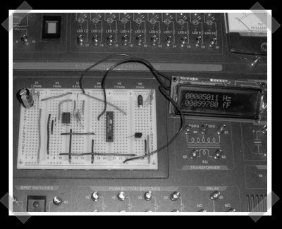
[Mike] sent in a project he’s been working on lately. This little circuit can measure the capacitance of a capacitor by generating a frequency that’s inversely related to the capacitance. He originally got it working with his o-scope, and followed up by building a stand alone version that uses an ATTiny2313 and a text LCD.
10 thoughts on “Simple Capacitance Meter”
Leave a Reply
Please be kind and respectful to help make the comments section excellent. (Comment Policy)


Cool…
so this could be used to find out if a capacitor has gone bad?
If the cap has an internal short, etc. then yeah it should tell you that the cap is bad. If its been in storage for a while, it may read a bit low but still be ok after reforming.
However, the main failure of electrolytics afaik is increase in ESR. This may affect the C reading of his circuit, but it doesnt look like it would be noticable.
But google ESR meter schematics if you require this, they are not too complicated to build.
Wow! This will help with my science project for school. This is exactly what I need, and it’s better than discharging a cap through a volt meter and timing the drop to 1v. Thanks!
awesome… I’m building one :)
I would like one too.I had the idea a few days ago so I have thought about it a little.Here’s what I want.
http://cgi.ebay.com/Smart-Tweezers-Capacitance-Inductance-Meter-DMM-agilent_W0QQitemZ250091364185QQcategoryZ25412QQrdZ1QQcmdZViewItem
It would be perfect for salvaging the unmarked surface mount capacitors on junk boards.
But if I built my own I want one to attach to my multimeter that converts to resistance or voltage.The circuit they show the 555 timer is doing most of the work .It could probably be adapted to anything that could do the time to capacitance conversion and display.Nice work to the designer though for keeping at it till it was done.
very handy!
Another good design for an LC meter is this one:
http://www.cappels.org/dproj/nlglcm/Pretty%20Good%20LC%20Meter%20Project.html
or this:
http://www.antennex.com/Sshack/aade/specs.htm
(schematic at end – also includes theory of operation)
@ledtester
I saw the first one when I was designing my circuit, but neither the design nor the math behind it is easy. With the second one, the design is simple, but has a higher parts count, even though the math is easier. With mine, all the equations I use can be found from the basic formula t=R*C. Just solve for a different variable, and you have a relatively simple equation.
@person
If your multimeter has frequency counting, use that, and solve the equation 1/(freq*R)=C, where R is the sum of the values of r1 and r2. This is how I did it when I was using my scope (using just the frequency function), and it works very well. If you want voltage, look at this: MRF24J40-I/ML, it’s a Frequency to Voltage converter in a DIP package, I don’t know if that’ll work entirely, but my samples should arrive next Monday, so I’ll know then.
Hey, that’s the radioshack 300-in-1 kit! I have one of those…