Flute Now Included On List Of Human Interface Devices

For decades now, we’ve been able to quickly and reliably interface musical instruments to computers. These tools have generally made making and recording music much easier, but they’ve also opened up a number of other out-of-the-box ideas we might not otherwise see or even think about. For example, [Joren] recently built a human interface device that lets him control a computer’s cursor using a flute instead of the traditional mouse.

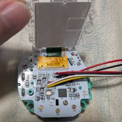
Rather than using a MIDI interface, [Joren] is using an RP2040 chip to listen to the flute, process the audio, and interpret that audio before finally sending relevant commands to control the computer’s mouse pointer. The chip is capable of acting as a mouse on its own, but it did have a problem performing floating point calculations to the audio. This was solved by converting these calculations into much faster fixed point calculations instead. With a processing improvement of around five orders of magnitude, this change allows the small microcontroller to perform all of the audio processing.

[Joren] also built a Chrome browser extension that lets a flute player move a virtual cursor of sorts (not the computer’s actual cursor) from within the browser, allowing those without physical hardware to try out their flute-to-mouse skills. If you prefer your human interface device to be larger, louder, and more trombone-shaped we also have a trombone-based HID for those who play the game Trombone Champ.

Garage Door Automation With No Extra Hardware

Home automation projects have been popular as long as microcontrollers have been available to the general public. Building computers to handle minutiae so we don’t have to is one of life’s great joys. Among the more popular is adding some sort of system to a garage door. Besides adding Internet-connected remote control to the action of opening and closing, it’s also helpful to have an indicator of the garage door state for peace-of-mind. Most add some sensors and other hardware to accomplish this task but this project doesn’t use any extra sensors or wiring at all.

In fact, the only thing added to the garage door for this build besides some wiring is the microcontroller itself. After getting the cover of the opener off, which took some effort, a Shelly Uni was added and powered by the 12V supply from the opener itself. The garage door opener, perhaps unsurprisingly, has its own way of detecting when the door is fully open or closed, so some additional wire was added to these sensors to let the microcontroller know the current state. Shelly Uni platforms have a WiFi module included as well, so nothing else was needed for this to function as a complete garage door automation platform.

[Stephen] uses Home Assistant as the basis for his home automation, and he includes all of the code for getting this platform up and running there. It wouldn’t be too hard to get it running on other openers or even on other microcontroller platforms; the real key to this build is to recognize that sometimes it’s not necessary to reinvent the wheel with extra sensors, limit switches, or even power supplies when it’s possible to find those already in the hardware you’re modifying. This isn’t always possible, though, especially with more modern devices that might already be Internet-connected but probably don’t have great security.

Saving PIC Microcontrollers With DIY Programmer

When working on a project, plenty of us will reach for an Atmel microcontroller because of the widespread prevalence of the Arduino platform. A few hackers would opt for a bit more modern part like an ESP32. But these Arduino-compatible platforms are far from the only microcontrollers available. The flash-based PIC family of microcontrollers is another popular choice. Since they aren’t quite as beginner or user-friendly, setting up a programmer for them is not as straightforward. [Tahmid] needed to program some old PIC microcontrollers and found the Pi Pico to be an ideal programmer.

The reason for reaching for the Pico in the first place was that [Tahmid] had rediscovered these decade-old microcontrollers in a parts bin but couldn’t find the original programmer. Thanks to advances in technology in the last ten years, including the advent of micropython, the Pico turned out to be the ideal programmer. Micropython also enables a fairly simple drag-and-drop way of sending the .hex file to the PIC, so the only thing the software has to do is detect the PIC, erase it, and flash the .hex file. The only physical limitation is that the voltages needed for the PIC are much higher than the Pico can offer, but this problem is easily solved with a boost converter (controlled by the Pico) and a level shifter.

[Tahmid] notes that there’s plenty of room for speed and performance optimization, since this project optimized development time instead. He also notes that since the software side is relatively simple, it could be used for other microcontrollers as well. To this end, he made the code available on his GitHub page. Even if you’re more familiar with the Arduino platform, though, there’s more than one way to program a microcontroller like this project which uses the Scratch language to program an ESP32.

TMS 1000 Microcontroller - By Antonio Martí Campoy - Own work, CC BY-SA 4.0

The Early History Of The Microcontroller: It Came From Texas

Ti’s presentation of the rapid integration of calculator chips.

Although for most generations alive today the era of microcontrollers (MCU) feels like it starts somewhere with the Intel 8051 and AVR MCUs, the history of these self-contained computing marvels that are now found just about anywhere begins long before those were even conceptualized. In a recent article titled Tiny Computers From Texas, [Babbage] goes through this early history of what would ultimately become such an integral part of daily life.

An MCU is defined as a small, self-contained computer, which requires few to no external components to function. This contrasted with the more traditional MPUs, or microprocessor units, where a computer was assembled out of one or more MPUs, I/O chips, memory SRAM and so on. It’s perhaps little surprise that the drive towards MCUs was the result of primarily the calculator market, where competing firms were trying to upstage each other with higher levels of integration into as few chips as possible, while driving down costs and power usage.

Ultimately, the Texas Instruments TMS 1000 was the first true MCU that got produced in large volumes after its release in 1974. Moving beyond calculators, the TMS 1000 found its way into toys, including the Speak & Spell – which uses another Ti chip (TMS 5100) for the voice synthesis – so that today any toy can be interactive in exciting and often noisy ways.

Back in 2020 we took our own affectionate look at this chip.

Wio Terminal Makes Passable Oscilloscope

There was a time when getting a good oscilloscope not only involved a large outlay of capital, but also required substantial real estate on a workbench. The situation has improved considerably for the hobbyist, but a “real” scope can still cost more than what a beginner is looking to spend. Luckily, plenty of modern microcontrollers are capable of acting as a basic oscilloscope in a pinch, provided there’s a display available to interface with it. Combined with the right software, the Wio Terminal looks like a promising option.

The Wio Terminal is a platform gaining some popularity due to its fairly capable SAMD51 microcontroller and also its integration with a display and a number of input buttons. On the hardware side, [mircemk] mounted the Terminal in a convenient vertical orientation and broke out a pair of connectors for the inputs.

But it’s the software that really makes this project work. [Play With Microcontroller] originally developed the firmware for the PIC24 back in 2017, but ported the code over to the Wio Terminal a couple years back. Noting that the microcontroller is not particularly fast, the project doesn’t exactly match the specifications or capabilities of a commercial unit. But still, it does an impressive job of recreating the experience of using a modern digital scope

The Wio Terminal is a device we’ve seen around here for a few unique projects, among them a device for preventing repetitive strain injuries while using a computer mouse and another that is a guide for game development in MicroPython. And if you’re just itching to port oscilloscope software to accessible but under-powered microcontrollers, be sure to check out [mircemk]’s other oscilloscope projects like this one built around the STM32 microcontroller.

Continue reading “Wio Terminal Makes Passable Oscilloscope”

Two-Channel Guitar Stomp Box Makes Momentary Switches Latching

When we first saw [Maarten Tromp]’s article about a “momentary latching switch” for guitar effects pedals, we have to admit to being a bit confused. When it comes to push-button switches, “momentary” and “latching” seem to be at odds with each other, with different mechanisms inside the switch to turn one into the other. What gives?

As it turns out, [Maarten]’s build makes perfect sense when you consider the demands of a musical performance. Guitar effects pedals, or “stomp boxes,” are often added to the output of electric guitars and other instruments to change the signals in some musically interesting way. The trouble is, sometimes you only need an effect for a few bars, and the push-on, push-off switches on many effects pedals make that awkward.

[Maarten]’s idea was to build a stomp box with momentary switches that act as inputs to an ATtiny2313 microcontroller rather than directly controlling the effect. That way, a bit of code can determine how long the switch is tapped, and activate a relay to do the actual switching accordingly. A short tap of the button tells the microcontroller to latch the relay closed until another tap comes along; a long press means that the relay is held open only as long as the button is held down.

Yes, he could have used a 555, a fact which [Maarten] readily acknowledges, but with some loss of flexibility; he currently has the threshold set at 250 milliseconds, which works for his performance style. Changing it would be a snap in code, as would toggling the latching logic. A microcontroller also makes expansion from the two-channel setup shown here easier.

Looking for more effects pedal action? We’ve got a bunch — a tube-amp tremolo, an Arduino Mega multipedal, a digital delay line. Take your pick!

Adding Temperature Sensor Functionality To The CH32V003 MCU

As cheap as the WCH CH32V003 MCU is, its approximately $0.10 price tag looks far less attractive when you need to start adding on external ICs for missing basic features, such as temperature measurement. This is a feature that’s commonly found on even basic STM32 MCUs. Fear not though, as [eeucalyptus] shows, you can improvise a working solution by finding alternative sources that can act as a thermometer.

Plot of the temperature measurement using the improvised CH32V003 -based temperature sensor. (Credit: eeucalyptus)

The CH32V003 is a low-end, 32-bit RISC-V-based MCU by the China-based Nanjing Qinheng Microelectronics, commonly known abbreviated as ‘WCH’, and featured on Hackaday previously. Although it features a single-core, 48 MHz CPU, its selection of peripherals is fairly basic:

So how do you create an internal temperature sensor using just this? [eeucalyptus] figured that all that’s needed is to measure the drift between two internal clocks – such as the LSI and HSI – as temperatures change and use this to calibrate a temperature graph.

Unfortunately, the LSI isn’t readily accessible, even through the Timer peripheral. This left the AWU (automatic wake-up unit) which also uses the LSI as a clock source. By letting it go to sleep and wake up after N LSI cycles, the AWU enabled indirect access to the LSI.

Internal diagram of the CH32V003 MCU. (Credit: WCH)

After calibrating against room temperature (~22 °C) and ice water (0 °C), a temperature plot was obtained, which could conceivably be somewhat accurate. As [eeucalyptus] warns, this is a kind of calibration that likely differs per MCU, and no attempt to quantify the absolute accuracy of this method has been made yet. Even so, as a crude temperature measurement, it might just be good enough.