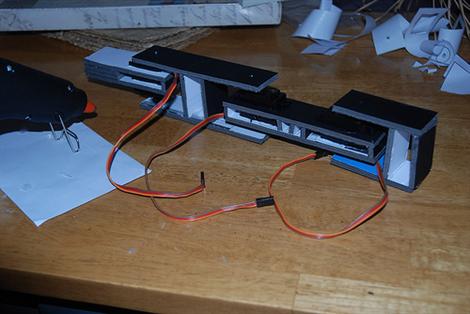
[Lucky Larry] posted some pictures to the Hack a Day flickr pool that caught our eye. He made a quick and cheap servo driven arm. Constructed from foam board and some hobby servos, he’s using an Arduino for the brains. You can download the pattern for the arm pieces as well as the code on his site.
He ultimately finds that he has positioning issues that he blames on the cheap servos. You can see in the video on his site that the circles it is drawing are drifting one direction.


I think it’s more likely that the drift is caused by poor tolerances in the foam board construction, movement of the base of the arm, movement of the writing surface, or some combination of those. Otherwise, I think it’s a good design and good instructions for adding a 2nd pivot-point to the servos.
err, I meant, deformation of the foam board (not poor tolerances). Sorry
Yea that and people tend to not have a reasonable idea of accuracy, like the guy I saw yesterday wanting to achieve 0.001 degree steps
You can see the base of the arm moving. I am pretty sure that is the cause of the circle being inconsistent. If he bolts it down, it may yield better results. Either way, I love see cheap alternatives to expensive projects!
Hey there,
Just seen this :) The reason why I blame the servos is even without the foamboard they fail to measure 1 degree properly – they tend to sweep around until they settle on the correct measurement. very odd and if you set the servo to 90 degrees that point will change a few degrees each time.
The foamboard is actually suprisingly solid providing there is no significant weight on the end actuator – the weight of the arm is used to force the pen to the paper. However I’ve not used the arm alot and with repeat use the foamboard wont last, so now I know its working (kind of) I’ll rebuild with better materials.
The base did move around alot, but because i’d taped down several sheets of paper but not all that well and as the pen caught in the paper edges, the base moved. (also the video is after its been runnign for a while)
Other thing I think you can see is only 2 joints move, the 3rd one nearest the pen can’t draw enough power.
Hey, great work! I’m doing a 4-legged spider with foam board, it’s indeed a material with some potential. I’m using pieces of wire and rigid-wire as fasteners and articulated joints.
heh.. now where did i put that linear hall effect sensor?
seems to me that a relatively simple circuit could replace the (temperamental) servo pot with a robust and reliable non contact sensor based on two magnets at the ends of the servo positioner with the poles opposing (i.e. north at one end and south at the other)
for small cheap mini magnets harvest them from broken cdrom drives (laptop ones are best) and superglue to the relevant points.
hope this helps someone..
bothersaidpooh – I’ve never even thought or eard of this before, is there any further info?
Njay – send me the links to the spider bot! :) I’d love to see that.
I know a guy doing the hall effect sensor + motor. It’s good for knowing where it is positioned (which is what we want), but not perfect for putting it in a special place.
Not sure why really.
Quit NOT posting videos, hack-a-day, jeez!