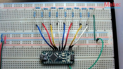
Have you ever built a Digital to Analog Converter before? This is a circuit that can take the 0 or 5V coming off of several digital logic pins, combine them together, and spit out one analog voltage that represents that value. If you’ve never made one, here’s your chance. [Collin Cunningham] over at Make put together another lab video about DACs which we’ve embedded after the break.
The circuit above uses an R-2R resistor network – often called a resistor ladder – which you can learn much more about from the reference page that [Collin] links to. Although a DAC in an IC package is by far the most commonly found application, we do see these R-2R networks in audio hacks from time to time.
[youtube=http://www.youtube.com/watch?v=b-vUg7h0lpE&w=470]


Very clear and simple explanation!
Thanks ;)
could this be done via PWM using one pin one resistor and 1 capacitor?
@1337
Sure, it’ll just be sawtoothy instead of stairsteppy.
Nice & clear explanation!
I recently wrote a review on the various DAC solutions, covering also the R2R. It’s also Arduino-oriented, but of course it works also with other controllers. In addition to the R2R, there’s a handful of other alternatives.
If interested, you can read it at embeddednewbie.blogspot.com
Damn, that sound in the background is so irritating! Great vid though :)
I ran a workshop last week and a 10 year old came up with a DAC design I’d never thought of: a LED for each bit and an LDR to pick up the signal. With the LEDs spaced correctly you could get a reasonably accurate response (the LED closest to the LDR functions as the MSB, the furthest would be the LSB). We used his to make a little melody generator – I’ve put the schematic on my blog.
I’d heard about resistor ladder DAC’s before but never tried building one until I saw this, just realized how simple it was and tried it. Instead of 8 micro pins I used a 74HC595 shift register and then shift each byte in. I used 1K and 560 ohm resistors because it’s all I had but the output is surprisingly clean and smooth. Now I just need to modify my code to produce a sine wave instead of a sawtooth wave.
or you could use an analog adder.
“Worth noting: If you’re looking for precision, you’re best off sticking with premade DAC ICs. Resistor tolerance alone can have a massive influence on an R-2R DACs output.”
Worth stressing; a valuable demonstration, but in practical terms this approach is limited to about 6 bits, however for only $5 you can get the DAC0800 which is monotonic over 8 bits and has bilateral current source/sink outputs.
@Rich Decibels – give that kid a gold star and “Win!” button!
Hehe, I’ve done this. Easy and fun. This is one step away from a cool micro controller synthesizer. You can even examine the waveforms (assuming you’re generating audio) by recording the audio on mic in and looking at it in something like audacity.
I made a resistor ladder DAC to use with a gameboy emulator over a PC parallel port.
It was pleasingly noisy, and really easy.
I had fun with this a year or so ago, with an Arduino mini. I had two outputs hooked up to my oscilloscope and wrote a couple of programs to draw pictures on the CRT. It was neat getting my ghostly visage on an oscilloscope :-D
http://id.motd.org/pivot/entry.php?id=10
I’m not quite understanding how this DAC works. It appears to be like a resistor voltage divider.
0 = 0v and 256 = 5v.
So the most significant bit should be 2.5v. Then 1.25v, …
Each pin has 20k for r1, and another value for r2, leading to ground. For the rightmost bit in his schematic (msb), r2 is 20k. So that bit will be 0 or 2.5v. But the next bit has 30k as it’s r2 value. 20/(30+20) * 5v = 2v when it’s on. and then the next one is 40k, so that would be 1.67v. And it seems logical to me that you just add up the collective voltages, but clearly I’m misunderstanding something.
Could somebody explain this to me? It would be greatly appreciated!
Is the output signal generated in the format required by an amplifier? In other words can i generate a sine wave and hear it out my speakers?
helped me a lot, thanks!
Ah, those memories from the 90th!
Build a resistor ladder, connect it to your parallell port on the PC, and play Pinbal Fantasy, Nuke Nukem and Sierra games. Even listening to MOD and S3M files in Fast Tracker II. <3
https://en.wikipedia.org/wiki/Covox_Speech_Thing