Successive approximation register ADC

Homebrew Circuit Explores The Mysteries Of Analog-to-Digital Conversion

When it comes to getting signals from an analog world into our computers, most of us don’t give much thought to how the hardware that does the job works. But as it turns out, there are a number of ways to skin the analog to digital conversion cat, and building your own homebrew successive approximation register ADC is a great way to dispel some of the mystery.

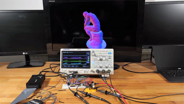
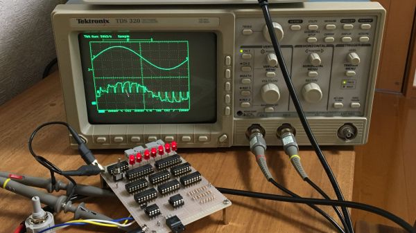
From his description of the project, it’s clear that [Mitsuru Yamada] wasn’t looking to build a practical ADC, but was more interested in what he could learn by rolling his own. A successive approximation register ADC works by quickly cycling through all possible voltage levels in its input range, eventually zeroing in on the voltage of the input signal at that moment and outputting its digital representation. The video below shows how the SAR ADC works visually, using an oscilloscope to show both the input voltage and the output of the internal R-2R DAC. The ADC has an input range of 0 V to 5 V and seven bits of resolution and uses nothing but commonly available 74xx series logic chips and a couple of easily sourced analogs for the sample-hold and comparator section. And as usual with one of his projects, the build quality and workmanship are impeccable.

We love these sorts of projects, which are undertaken simply for the joy of building something and learning how it works. For more of [Yamada-san]’s projects, check out his 6502-based RPN calculator, or the serial terminal that should have been.

Continue reading “Homebrew Circuit Explores The Mysteries Of Analog-to-Digital Conversion”

Back To Video Basics With An ESP32 VGA Display

In a world where standards come and go with alarming speed, there’s something comforting about VGA. It’s the least common denominator of video standards, and seeing that chunky DB15 connector on the back of a computer means that no matter what, you’ll be able to get something from it, if you can just find a VGA cable in your junk bin.

But that’s the PC world; what about microcontrollers? Can you coax VGA video from them? Yes, you can, with an ESP32, a handful of resistors, and a little bit of clever programming. At least that’s what [bitluni] has managed to do in his continuing quest to push the ESP32 to output all the signals. For this project, [bitluni] needed to generate three separate signals – red, green, and blue – but with only two DACs on board, he had to try something else. He built external DACs the old way using R/2R voltage divider networks and addressed them with the I2S bus in LCD mode. He needed to make some compromises to fit the three color signals and the horizontal and vertical sync pulses into the 24 available bits, and there were a few false starts, but the video below shows that he was able to produce a 320×240 signal, and eventually goosed that up to a non-native 460×480.

It’s a pretty impressive hack, and we learned a lot about both the ESP32 and the VGA standard by watching the video. He’s previously used the ESP32 to build an AM radio station and to output composite PAL video, and even turned his oscilloscope into a vector display with it. They’re all great learning projects too.

Continue reading “Back To Video Basics With An ESP32 VGA Display”

Hackaday Trims Its Own Resistors

There are times when you might want an odd-value resistor. Rather than run out to the store to buy a 3,140 Ω resistor, you can get there with a good ohmmeter and a willingness to solder things in series and parallel. But when you want a precise resistor value, and you want many of them, Frankensteining many resistors together over and over is a poor solution.

Something like an 8-bit R-2R resistor-ladder DAC, for instance, requires seventeen resistors of two values in better than 0.4% precision. That’s just not something I have on hand, and the series/parallel approach will get tiresome fast.

Ages ago, I had read about trimming resistors by hand, but had assumed that it was the domain of the madman. On the other hand, this is Hackaday; I had some time and a file. Could I trim and match resistors to within half a percent? Read on to find out.

Continue reading “Hackaday Trims Its Own Resistors”

Fun Audio Waveform Generator Is More Than The Sum Of Its Parts

[Joekutz] wanted to re-build an audio-rate function generator project that he found over on Instructables. By itself, the project is very simple: it’s an 8-bit resistor-ladder DAC, a nice enclosure, and the rest is firmware.

[Joekutz] decided this wasn’t enough. He needed an LCD display, a speaker, and one-hertz precision. The LCD display alone is an insane hack. He reverse-engineers a calculator simply to use the display. But instead of mapping each key on the calculator and typing each number in directly, he only taps the four 1, +, =, and clear keys. He can then enter arbitrary numbers by typing in the right number of ones and adding them up. 345 = 111 + 111 + 111 + 11 + 1. In his video, embedded below, he describes this as a “rather stupid” idea. We think it’s hilarious.

Continue reading “Fun Audio Waveform Generator Is More Than The Sum Of Its Parts”

Logic Noise: Digital To Analog With An R-2R DAC

Making sound with digital logic usually calls for a Digital to Analog converter. Building one can be very simple, and the sound quality out of an R-2R Ladder is actually pretty good.

In the last edition of Logic Noise, we built up a (relatively) simple VCO — voltage-controlled oscillator — that had roughly one-volt-per-octave response. I even demonstrated it working mostly in tune with another synth’s keyboard. But what if you don’t have a control-voltage keyboard sitting around or you want to combine all of the logic-based circuits that we’ve been building with other circuits under voltage control? That’s where the digital to analog (DAC) voltage converter comes in.

Continue reading “Logic Noise: Digital To Analog With An R-2R DAC”

Your First Digital To Analog Converter Build

Have you ever built a Digital to Analog Converter before? This is a circuit that can take the 0 or 5V coming off of several digital logic pins, combine them together, and spit out one analog voltage that represents that value. If you’ve never made one, here’s your chance. [Collin Cunningham] over at Make put together another lab video about DACs which we’ve embedded after the break.

The circuit above uses an R-2R resistor network – often called a resistor ladder – which you can learn much more about from the reference page that [Collin] links to. Although a DAC in an IC package is by far the most commonly found application, we do see these R-2R networks in audio hacks from time to time.

Continue reading “Your First Digital To Analog Converter Build”

Halloween Props: Voice-changing Daft Punk Costume

[Dr. West] shared his Halloween costume with us; a Daft Punk inspired voice-changing helmet. He stared with a motorcycle helmet, cutting out a hole in the back for a sub-woofer speaker. Inside there’s an old computer mic and the amp circuitry for a portable stereo system. An Arduino is used to pick up the wearer’s voice from the microphone and perform the digital signal processing. Once the alterations have been made the signal is sent to an R-2R resistor ladder to perform the digital to analog conversion, and onto the amp for broadcast. Hear the result in the video after the break.

The rest of the helmet is window dressing. He found some kind of auto-body repair product called flex-edging to use as metallic hair. Those fins are accented with strings of red and blue LEDs. The faceplate finishes the look using speakers from the stereo system and a tinted visor.

He wan’t going for a replica, but we think his creation would be right at home with the look of the original.

Continue reading “Halloween Props: Voice-changing Daft Punk Costume”