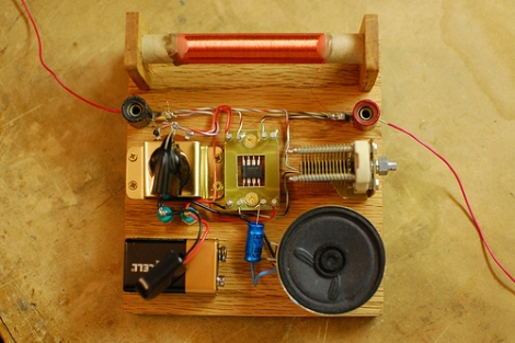
[Eric] recently built an AM radio based on a 555 timer, and posted a few pictures to the Hack-a-Day Flickr pool. He used the 555 timer as an AM demodulator and power amplifier in order to drive the speaker. A hand-wound inductor is used to tune the signal which is then superimposed over the ramp signal produced by the circuit he built. [Eric] points out that he chose a CMOS 555 timer because of its superior performance in this particular application since the timer is used in a bit of a nontraditional manner. He shared his circuit diagram as well as a great video walking through each part of his design, finishing off with a demonstration of the radio, which can be seen below.
This is yet another great project that will be entered in the 555 Design Contest – simple and elegant. We love seeing these, so keep them coming!
If you want to see more cool projects made by Hack-a-Day readers, be sure to check out our Flickr pool as well as the forums.
[youtube=http://www.youtube.com/watch?v=YC72J2VOSH0&w=470]


A nice example of true craftsmanship and innovative tinkering. Nice job!
Hi, using the bipolar 555 works too? or not at all.
Great design! And very well made !
@kabukicho2001, the CMOS version is used due to the smaller current required for the inputs.
The bipolar version would simply kill the LC circuit…
One possible upgrade to this would be a 9v transformer. That way you can just plug it in with a 3 pronged plug to the outlet (and still have a solid earth ground). A 12v would probably work just as well (and be cheaper). But otherwise, Great build.
ANOTHER 555 TIMER?! Can’t anyone build anything without a 555 IC?
Remember the days before the current 555 craze, when the microcontroller-haters complained when any project used a microcontroller in cases that a 555 timer could suffice (though almost always with less flexibility and room for improvement later).
Sarcasm mode := off.
Bravo. Nice build. I especially like the way the 555 is featured in the center.
Neat! :) Hats off! :)
Awesome design, keep ’em coming man!
i just did this last night, by accident.
Interesting concept. I bet it could be modified in to the receiver / transmitter for one of microcontroller projects seen here on HaD.
That dude totally creeps me out.
Hmm… Now for a 555 transmitter so I can have 555 walkie-talkies (:
But I think making an FM transmitter/recever would be fairly straight forward also. An amplified old carbon mic/signal from the antena to adjust the frequency.
Maybe multiple 555’s and send digital data (:
Hmm maybe shift registers that latch in and out a series of resistors to play happy birthday
(but how to mount a circute like that in a card… Thinking out loud again)
use the “unused” CV input and drive from an electret microphone, and disconnect the speaker.
Ought to work, just use the LC circuit as a transmitter.
Nice work. I would be surprised if this doesnt claim some prize or another.
Very clever! I’m impressed! As a note to newcomers, be very wary about thinking of AC ground as “near to earth ground”. In the RF world a good ground is just as important as your antenna, and who knows what else AC ground is used for! Lights, other electronics, air conditioners – all sorts of things tie into the same wires which may push noise back into your radio. Living on the 2nd floor of an apartment, my AC ground is noisy as can be! I have a radial system of balanced dipole antennas hanging on my ceiling inside my apartment to try to avoid using AC ground as ground. Also, that variable capacitor is expensive and a little hard to find (I know!) – a configuration with a varactor diode and potentiometer would be cheaper, easier to access for anyone to recreate, and allow voltage controlled (microcontroller?) tuning. I use power rectifier diodes successfully for this purpose! Food for thought… but again, awesome project. You really nailed the heart of the competition!
excellence good