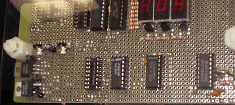
We’re always impressed when a piece of hardware is torn apart, rebuilt and ends up exceeding the capabilities of the original device. [Dave] and [Will]’s home-built TIG welder is no exception to that rule.
When [Dave] and [Will] started working on converting a simple AC stick welder to a welder with every function imaginable, they decided to keep it simple. After looking at some high-price commercial welders they came up with a list of features they wanted to have and decided to implement this in TTL and CMOS logic. The guys didn’t want to go with a microcontroller solution because not everyone can code, and discrete chips are very easy to troubleshoot given minimal tools.
For the high voltage part of the build, the original flyback transformer was replaced with a neon sign transformer and homebrew spark gap and capacitor. The plans for a homebrew spark gap and cap didn’t quite work out so they were replaced with commercial units. The guys included schematics and a PCB layout (PDF warning) of their build. It’s always great to see an amazing logic chip build, and improving an existing tool never hurts.
Thanks to [Franci] for sending this one in.


Thought I had a blue screen of death when I clicked their link ^^
Jup – the project itself is nicely done … but this color-combination kinda sucks ;-)
I don’t know about other browsers, but chrome can edit HTML live: right click > inspect element then change the colours to whatever you want :D
I e-mailed the builder (project page was last updated 5 years ago) asking about any additional changes. Also, requested photos of sample welds.
I’ll post any response received.
There doesn’t appear to be a parts list. If anybody has compiled one, please share it!
could have swarn i have seen this here before
Nice to see somebody else using the “pad per hole, plated through hole” proto-board.
That’s the stuff I use and it’s great! More expensive though, but looks better, works better. The pads don’t pop off just by looking at it too hard. You have to really man-handle them to lose a pad.
Interesting, I’ll have to try those boards sometime. Pads always pop off of my boards and it makes me crazy!
Wow hackaday, not been updated since 2006? Yeah its a great project, but no idea if/how well it works, sample welds, etc.
I did build a tig welder off the casano high-frequency hack that got posted up a while back and some diagrams from the hobart weldtalk messageboards, as much as I wanted to do something more along these lines that website was of no help whatsoever.
What are those double holes in the PCB layout(see pdf) on the header on the right side of the board?
Why are they there?
@Andrew : Which is why you should use a temp. controlled iron :)
Happy! I have a chinese dc TIG. It had no foot control so I built one out of an old fuzz-wah pedal and it’s much better, but I want to weld aluminum, so I need AC and variable DC balance. I’ve been plotting to upgrade it to AC with pulse and DC balance functionality using an arduino to read the control pots and control the frequency and duty cycle, but I’ve been struggling with how to couple my h-bridge in to the existing welder’s output without having the HV/HF start circuit blow the outputs. Maybe I can rip off their output circuit.
I really don’t wanna be mean, but you already posted this five years ago: http://hackaday.com/2006/03/23/commercial-grade-tig-welder/
BTW, it would be very very nice to see the project updated.
I received a reply to my e-mail:
“it is unfortunate but I have zero time now to update the design and all the info I have is already on the old page.
I think you will find given that the design is now so old you could nowadays pick up a TIG unit (inverter style) far cheaper than building one !”
– Dave
looks more like an oil furnace ignition transformer to me than a neon sign xformer