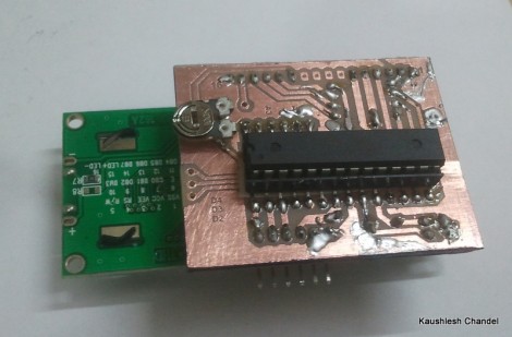
[Kaushlesh Chandel] prototyped a few projects on his Arduino that use an HD44780 Character LCD. Wanting to keep these projects in one piece, but not sacrifice his Arduino board, so he etched his own LCD backpack that is Arduino compatible. If you’ve never made it past the Arduino board to build a module that only uses the parts you need for a project, this is a great source of inspiration for you to give it a try.
The design that [Kaushlesh] drew up is quite simple. It connects directly to the single in-line header of the character LCD. It looks like he’s using the 4-bit mode for addressing that display, which leaves you with quite a few pins (both digital and analog) to work with in the future. The important components rolled into his design are the chip itself, an ATmega8/168/328, the crystal to make sure it is running at the correct speed for Arduino timing, and a trimpot for adjusting the contrast on the display. The final feature you’ll want to be sure to include in your own design is a pin header for programming the chip via an FTDI cable.
Never etched your own PCB before? Give our PCB fab tutorial a try.


Maybe there is nothing new here, but I like the presentation and the toner transfer link, plus the idea that he left the remaining data lines available for a header.
A fellow hacker [Thomas Flummer] at my local Hackerspace [Labitat] did a similar thing for a SMD soldering workshop, it’s a nice board too, building on the same ideas, extra I/O brought out too. http://www.hackmeister.dk/lcd-io-backpack/
I see the pot on that board (LCD contrast level) and I recognize the desire to keep pins open for other functions.
In my U/I projects I’ve been using one PWM pin to supply the contrast. The datasheet for the LCDs has 44780 pin 3 drawing way less than the 40ma current/pin allowed on the AVR.
If you want to keep the pin open, put a two way (three pin) jumper or DIP switch that allows you to choose where you draw your contrast from.
If you used pin 3 to pin 3, the code would be:
pinMode(3,OUTPUT);
analogWrite(3, 60);
On my MTC-16205D, PWM signal value of about 50 to 70 gives me ideal contrast with a 5V VCC. This is about .7 to .9 volts at the contrast pin.
Hey thanks for the valuable tips. Very much appreciated.
I am working on a 6.5 Digit DMM with Arduino that uses a GLCD. I hope I can use PWM for setting the LCD contrast that way.
Glad to help.
Make sure to check your datasheet for the LCD make/model. My 16×2 displays pull a maximum of 2.0 milliamps.
I just recently got an MTC-16205D LCD and I was trying to get started on initializing it and writing to it. Can you possibly help me get started or show me how you implemented it?
+1 On the PWM for contrast and backlight. It reduces your part count and makes it so you can adjust it on screen at anytime for different LCD’s. Of course you will want a small PNP transistor for the backlight.
I do the same thing with our I2C to LCD module.
http://www.oscsys.com/BrewTroller-I2C-LCD-Controller.html