Making a PCB is very simple; it does not consume a lot of time and the results look professional. After reading this How-To and watching the step by step video, you will be able to make your own PCB in your workshop using just a few inexpensive materials.
Many people use protoboard and point-to-point wire everything, but needing multiple copies of the same circuit is the reason that forces many away from using protoboard. After making your first circuit board, you might not point-to-point wire anything again!
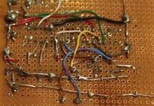
For your first circuit board, one goal is to keep the circuit single sided so you can etch using single sided copper clad. This will allow you to gain some experience before moving on to double-sided. If you need topside traces, simply run a few jumper wires on the top. There are many complete circuit layouts you could try like the Hack a Day design challenge winner.
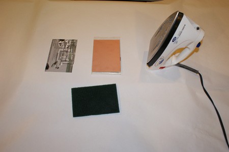
Here is a list of materials you will need to produce a single-sided board. With the exception of the copper clad and PCB drills, everything on this list is easily obtained at your local store.
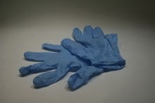
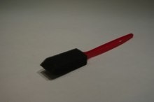
Materials: Muratic acid, common household hydrogen peroxide, safety goggles, good quality magazine pages (cut to 8×11), laser printer, single sided 1 ounce copper clad, a plastic container the board will fit in, soft plastic brush, clothes iron, lacquer thinner, rubber gloves, paper towel, tin snips, drill or rotary tool, PCB drill bits, Scotch Brite scrubbing pad, good ventilation, 5-gallon plastic pail full of water.
Now, here is how you do it:

Print the bottom side layer on a piece of paper from a high quality magazine. Use one actual page from the magazine, the thicker and shinier the magazine paper the better, but do not use the cover. You must use a laser printer, not an inkjet. If your printer uses ink cartridges and not toner cartridges, it will not work. If you do not have a laser printer, you can work around this by printing to white paper and using a photocopier set to the darkest setting to copy the layout to the magazine paper. If the paper jams in the printer, you are not using a thick-enough magazine page. Again, do not use the magazine covers, as they do not work.
Magazine pages are used because they work well, and they are cheap! The reason they work is because the paper is very glossy and the toner does not adhere well to the glossy pages. The printing used on the magazine page is ink and it does not come off, but toner does. Toner is actually a plastic polymer, and different toners may yield varied results. In our experience, a genuine HP toner cartridge was used with great success; an Office Max brand yielded poor results. The sole purpose of the toner is the protect the copper below it from etching away, you only want the uncovered areas to etch.
Next, wash your hands to remove any oils. Keep handling to a minimum once the pages are printed and do not touch the laser printing with your fingers; this could get oils on the printing. Keep pages as flat as possible.
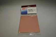
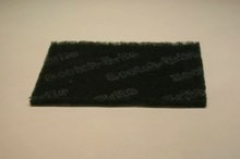
Very carefully, remove the copper clad from the packaging. Do not touch the copper surface for the same reason as above. You can cut the copper clad to size using a tin snip if needed. Use the Scotch Brite scrubbing pad to gently buff the surface (Scotch Brite is a popular brand of of plastic scrubbing pad meant to emulate steel wool). Do not use steel wool because it will embed steel into the copper. Clean off the residual dust with a slightly damp paper towel.
Find a hard, very flat, sturdy, heat resistant surface. Empty the water out of the clothes iron and set the iron on the hottest setting. Allow the iron to get hot.
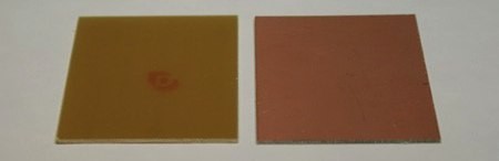
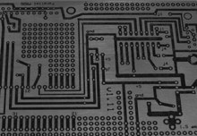
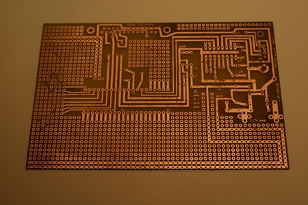
This is both side of a piece of copper clad. Place the blank side facing down and copper side facing up. Align printing/paper onto copper clad board with the printing facing the copper. Do not allow it to move.
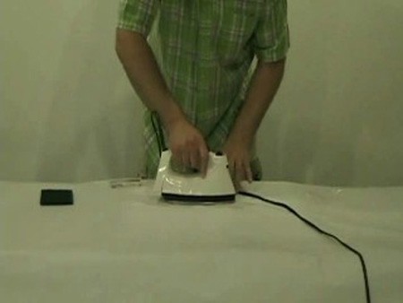
Firmly press the iron onto the back of the magazine paper, sandwiching it between the copper clad and the iron. Pressing hard without moving the iron, hold the iron perfectly still for one full minute. Do not move the iron at all during this minute, and push hard, really hard!
Then, for four more minutes, slowly move the iron around making sure to put a lot of pressure on the paper, but not allowing the paper to slide on the copper. When done, let the board fully cool before you move it at all. This will allow the toner to adhere to the copper and prevent you from being burned.
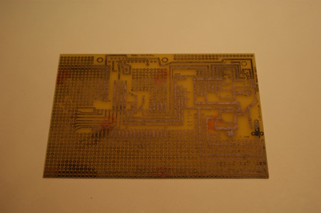
Put the board in cold water and let soak for five minutes. After five minutes, try to peel the wet paper from the board leaving only the toner/print from your laser printer. Only the toner should be left adhering to the copper. If the paper does not come off easily, let it soak in the water for a while longer. If necessary, rub with your finger to remove any paper, leaving only the toner. It’s ok if there are a few excess paper fibers stuck to the toner.
If you find not every trace adhered to the copper clad or it is misaligned, use lacquer thinner and paper towel to clean the toner from the copper board and start over. If the traces look good then move on. Inspect the traces carefully, however, because what you see now will be your finished product.
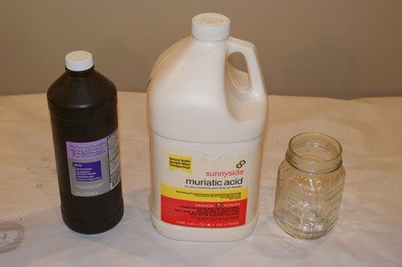
In a well-ventilated area with a fan, add 2-cups hydrogen peroxide to a plastic container. Gently pour in 1-cup Muriatic acid, to create the etching solution. Always wear goggles, gloves, and do not inhale the fumes. Do not use any metal containers, measuring cups, stainless steel sinks, or tools with this mixture as this mixture will aggressively etch metal. Acid safety, think “triple A”, for Always Add the Acid, it’s whatever is in the container that will end up splashing. This etching solution, while made with common chemicals, should command respect. It is dangerous to yourself and surroundings, treat it with respect. Ferric Chloride is another common etching solution, it is not a safer solution to use, both are equally dangerous.
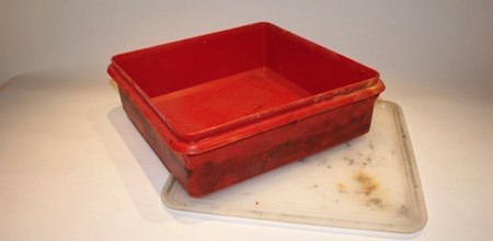
Put the board copper side up in the plastic container filled with etching solution. Use a soft plastic brush to gently wipe the board. You will notice the copper begin to dissolve. It takes about 3-4 minutes to get all the exposed copper dissolved. You just have to watch to make sure it is gone in all areas between the traces. Do not leave the board in the etching mix for too long as the traces will dissolve under the toner that is protecting them.
Wearing rubber gloves, take the board out of t
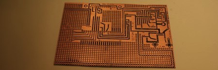
he etching solution and inspect it to see if all the exposed copper is dissolved. If it’s not, put the board back in and use the plastic brush to brush over this area. If it is dissolved, rinse the board under water for one minute washing it clean. Dry the board with a paper towel.
At this point, the solution is used-up because of all the copper that has been dissolved within it. Dispose of the solution by diluting it in a 5-gallon pail of water. When mixed with the 5-gallon pail of water, the acid level and copper content was well below test limits in the water sample we sent out to be analyzed (restrictions in your area may differ). You may further reduce the amount of copper in the solution by not etching areas of the board that are not required. Consider adding ground planes in large open areas, and using less etchant when making smaller boards.
Use lacquer thinner (paint thinner and acetone do not work well) and a paper towel to remove any toner left on top of the copper traces.
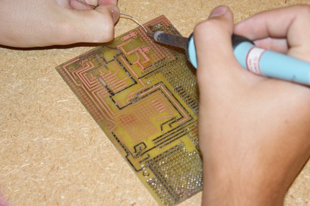
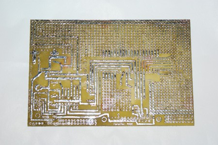
Tinning prevents the copper from oxidizing, which can make it hard to solder to in the future. If you choose, you can tin all the traces with solder and a soldering iron now. This actually makes drilling much easier because it helps to center the drill bit. Make sure to clean off excess flux if you do this. You could use Tinit to chemically plate the copper. Here is a different tutorial describing its use.
Drill all the holes for the through-hole parts using the correct size PCB drill bit and rotary tool. Drill large mounting holes with a normal drill. PCB drill bits are carbide and made to drill through fiber glass that would quickly dull standard bits. There are a few very common sizes of bits and these are often sold in packs. We use .0260″ for IC holes and .0310″ for resistors and caps.
Print out the top side silkscreen layer on magazine paper and iron this onto the top side, using the same processes as above. Again, run under water and peel off the paper. Now you have the component ID’s on the top side.
Here is a different video using essentially the same method:
You can make really nice PCBs of your own circuit design using this simple method, and we look forward to seeing your future projects using this method coming in on the tip line. Look for more How-Tos like this one in the How-To category.


Why tin the traces? This seems like a big waste of time
You need to tin traces in some cases to increase the current carrying ability of the traces without increasing trace width or if you don’t plan on using a solder mask to protect them from oxidation.
THANK YOU, THANK YOU, THANK YOU, THANK YOU, THANK YOU!
I’ve wanted a good redux on this for a while…
Drilling holes is reason #1 I don’t do at-home etching if I can avoid it. Even with a decent press, my impatience to finish up usually results in a pile of broken bits that could have paid for an expresspcb batch.
I use a small handheld drill, and I almost never break drilling bits.
This is a very nice tutorial that I am going to try this. Are all glossy magazines fine for this?
Gio
Great introduction to single sided PCBs for low complexity boards (thick traces).
Nevertheless, i’ll keep using the standard photoresist board + U.V. light. It needs essentially the same materials (U.V.(sun) Iron) and the results are far better, specially with SMT boards.
Anyway, a good tutorial for beginners!!
Great article. I’m glad to see that hack a day listen to its readers.
The major point is if you can get the pages to feed through your laser printer. If they are too thin you get paper jams.
I have to say this is a great how-to, very detailed, and multiple media format; video, pictures, and well written text. Plus it is not simple rehashed content.
I will try this just to see if I can do it. This how-to leaves me with the feeling I will be successful.
This is why I read hackaday, keep up the good work!
#3: you won’t end up with a pile of broken bits if you use a drill press at the correct speed. nevertheless, it still takes a lot of patience and since i’m not made of money i usually end up doing my own boards anyway. i must say, though, jason’s results from using a clothes iron are very good. i could never get anything decent from a clothes iron, now I use a modified laminator which works very well.
Nice article, but I’m not sure I agree with the statement that ferric chloride “is not a safer solution to use, both are equally dangerous.” But read the MSDS and decide for yourself. Don’t just go by the Wikipedia entries; they’re incomplete and inaccurate. Note, for instance, that ferric chloride solution prepared for PCB etching and ferric chloride itself have different properties; the Wikipedia article seems to focus on the latter.
@#3: I didn’t really have any problems, but I second the idea of a press. If you have one, or just have access to one (buddy who works at a shop can get you in for an hour, etc.), it greatly speeds up the work and you’re probably more accurate to boot. If you’ve got a Dremel already (and who here doesn’t?), you can get a press attachment/shell for pretty cheap, but I haven’t tried them myself so I can’t speak to quality.
Thank you Jason. Great tutorial, can’t wait to try it out.
Isn’t this etchant solution regenerative? Couldn’t you, rather than mixing with 5gal of water, just use an aquarium bubbler, or whatever, and just save it?
I mean, isn’t this the same end result as mentioned here: http://www.hackaday.com/2006/08/12/cupric-chloride-etching/
as well as here:
http://www.instructables.com/id/EUZET2WLCJEV2Z96TB/
If you don’t have a laser printer available, I’ve had some success with a couple coats of sharpie marker. It’s not nearly as neat, or reliable, but works in a pinch. I would guess that paint marker or something similar would work well too.
nice. i have never been able to get near as nice of boards by toner transfer. as far as drill bits go a mounted dremal tool is a life saver because the higher spindle speed (smaller the bit the faster). with a mounted dremal i have had no problems with bits down to .0145
How long it took to drill all the holes?
LOLL
I never used magazine to make pcb, I will try next time!
It is sort of free.
I don’t understand why you tin the trace. Like #1 said.
I do think it is a waste of time since after drilling you solder your component to the board. It is not like you are leaving the board ontouch for months. Even if it is tarnish, you can simply use your scrubbing pad.
thanks!
I suppose if you’re broke, or in a real hurry, this might appeal. But really, with services like http://www.batchpcb.com or http://www.pcb-pool.com, I really don’t understand why you’d bother sloshing about with toxic chemicals for mediocre results. The PCBs you get back from a fab house are so much better than what you can do at home. Things like solder masks (critical for SMT work) nice silk screens labels, dual sides with plated through vias. And if you’re willing to wait a couple of weeks, it’s not even that expensive. The required CAD software (Eagle, TargetCAD) is free if you’re willing to put up with a few restrictions. SparkFun.com has a nice tutorial on using Eagle to design boards (skip to page 8 in their “Beginning Embedded Electronics” tutorial).
I use this etchant too when I make pcbs. It works pretty good. I have a good tank made up to etch my boards in and eventually I will get it put up on my website, with 100 other projects I’m working on. Well done. Here is some good info I found a while back http://www.fullnet.com/~tomg/gooteepc.htm#1 and use toaster ovens as reflow ovens http://www.circuitcellar.com/library/print/0704/Lacoste_168/index.htm http://www.sparkfun.com/commerce/present.php?p=Reflow%20Toaster
why tin the traces?
why are component leads tin/lead plated?
most of us live within 1000 miles of salt water. copper 1oz traces corrode through in a surprisingly short amount of time under most conditions.
when you apply a green solder mask and solder it, there is _no_ exposed copper.
Dear Son,
That was a very nice video. But why didn’t they show your face. You are such a handsome boy, and have a cute smile. Please son, re-shoot the video with some close ups of your face. And call me sometime, won’t ya!
Love always, mom.
tinning is a great idea. tinning by hand is not.
just use liquid tin and dunk the board
The reason for tinning is 3 fold. First, drilling it makes it much easier to align the drill in the center of the hole. Second it makes it much easier to solder because it prevents oxidation. And third, it prevents the finished product from growing green and potentially failing due to close traces shorting due to growths. Think of the nastiest penny you have ever seen.
It does not take the long to tin with an iron maybe 2-5 mins as you can just spread it all around hap hazardly. My son who is 14 did it in 5 minutes and never soldered before this time.
It also only takes about 10 mins to drill all the holes I had in there. the drill press is set at 25k RPM and the carbide bit works really well at those speeds. It is easy to align the drill after you have tinned by hand.
#12 if you donât have a laser printer is would be best to photocopy your inkjet or go to kinkos or some place. Hand drawing circuits is not that much fun :)
#19 Mom, sorry I didnât focus on me for the video, the next video will be all about me,
#9 A normal drill press is far to slow. A high speed rotary is the best, such as a dremel drill press.
http://www.mytoolstore.com/dremel/drillprs.html
I agree with not tinning… the frustrations caused by a tarnished board are nothing in comparrison to the frustrations caused by closed holes from tinning accidents.
Ive done plenty of 20 second clean jobs on radioshack protoboards and the like. really, its very little effort.
dont get me wrong, a properly tinned board is nice to work with. but I dont have the patience to do it right, without closing at least a few holes.
p.s. another paper source is photo paper.. yeah, it is expensive, but thicker. I have not tried magazine paper. I’ll give it a try.
I use the same transfer method to etch copper platemetal, using electroetching in copper-sulfate. I have found cuso4 to be pretty aggressive on the toner, and usually lifts to toner off long before it etches as deep as I want.
@ myself: doesnt matter if the holes are closed if you tin >before< drilling holes.
Ranger, wouldn’t that whisker? Like, catastrophically?
reasons to use home etching;
1 – not everyone lives in the USA and even if they did, no one should settle for postponing a project development for days waiting for a prototype
2 – speaking of a prototype.. it is a “prototype” why pay money for a design that has a high risk of malfunctioning? testing circuit parts, as opposed to software solutions, are relatively easy.. you should build dirt cheap and quick solutions like this and exhaust every possible operating scheme for faults.. then, and only then, you can safely say you are spending money wisely..
I believe the next step in DIY prototyping is UV tank. I have been using this method and doing things with a clothing iron is just not reliable. What I want to do is, build my own UV tank (some guy built one using a scanner case afaik) use transparent paper for printing (not free but dirt cheap) and expose using UV. After that, I will use the procedures described in this tutorial.
If only someone made a cheap CNC drill for home use on projects like this. Actually, even better would be a laser cutter, which could of course also do holes.
There are videos on YouTube of a guy who made a basic laser cutter out of a DVD-RW laser…
another method for tranferring toner from regular paper to copperclad is just to use paint-thinner alone. tape on your printout onto yer board, then use a sponge or cloth saturated in thinner, wipe evenly across the back of the paper and lift up afterwards. if you mess up, try again.
My ideal (mostly untested) pcb prototyping setup (i’m actually working on it this week)
a) Inkjet Direct-to-Copper PCB Printer (http://techref.massmind.org/techref/pcb/etch/directinkjetresist.htm)
b) standard bubbler/heater pcb etching system w/fecl
c) Pebeo Vitrea for soldermask/silkscreen (and silkscreen?) (maybe dispensible using PCB printer?)
d) DIY high speed pcb drill press for holes(http://www.instructables.com/id/$30-High-Speed-PCB-Drill-Press/)
e) eyelets for thru-holes and vias (http://www.intl-eyelets.com/ or Keystone eyelets available on mouser)
f) tinnit for tin plating
g) (maybe?) Use laser printer or pcb inkjet to make solder paste mask on thin piece of copper clad; use acetone to remove FR-4
Harbor Freight sells a 50-pack of assorted (probably resharpened) Carbide bits for $13 online. The stores generally have 10-packs for somewhere around $5. Buy a couple and you probably have all the bits you need. Works great in my Dremel w/press at maximum speed. I have yet to break a single bit with this setup.
I haven’t had a large amount of success with toner transfer either, I have been using Staples photo paper on a Brother laser printer. I’ll have to try the magazine paper, but I’d really like to get a UV setup, as this seems to be a lot more consistent and able to make much finer traces.
The HCl/H2O2 etching solution works great, and with the right equipment (bubbler) can be regenerated. I don’t make many boards, so I generally just make a very small amount in a glad-ware container and heavily dilute it before dumping it.
Nice tutorial, but I started sending this work out to a company that specializes in short run prototype work a long time ago. Their results are much better than what I could achieve on my own and the cost isn’t that much more than doing it yourself. Add to that the fact that you don’t need to store hazardous chemicals and I can’t say I’d go back to DIY’ing it.
If you do still do it yourself, you could use your scotchbrite to remove the toner from the finished board. It would be one less chemical you would need to have on hand, anyway. Also, there’s no need to tin the traces. 2 seconds with a very mild abrasive on the oxidized copper and it will solder just like it was new.
there’s a magazine called Yachts International. Somehow I ended up with a free sub but the page quality is superb and 1 mag gives almost 100 pages. Adverts start around pg# 170. Long story short I’d just been tossing them but I will no longer!
Thanks!
For those wondering why do this type of fabrication try this:
My friends and I went to Cambodia last year to teach at a trade school. This was the method we ended up using since they can’t really order a pcb online. The biggest problem we came across was finding the acid to make the etchent, we went with the ferrous acid from a moto repair shop, and then guessing the mixing ratios (relying on our chem 101 skills), producing some not nice gas at first.
Otherwise it went great and the school invited us back for more advance work!
sir ,
please sand me a copy of vidio of etching ,it will help me to etch my pcb
Yeahhh Magazine Paper! I use magazine in the process for a long time…
Once we was out of transparent plastic when i see a microsoft magazine over the table…
Good How-to
You can get more help on making PCBs on my Yahoogroup, Homebrew_PCBs.
http://tech.groups.yahoo.com/group/Homebrew_PCBs/
Toner transfer, commercial PCB makers, using the software, direct inkjet resist printing, CNC milling, photoetching, different etchants (how to make and use them), etc.
I started the group so there would be one place to start. The links section is well populated.
What to do if you finished making your boards? I presume you cant just dump everything in the sewers?
When using the muritic acid etchant, you don’t pitch the “waste” solution. It only gets more effective as you go, so you keep it for the next batch.
When it starts turning brown, you bubble it with air. If that doesn’t turn it green again, you add a little more muritic acid.
You *really* don’t want to dump this in the sink though. It’ll eat the stainless steel like nobody’s business, and is very bad for marine life due to the copper chlorides in the solution.
I loved o: Etch a single sided PCB – Hack a Day!
I have had very good luck using my wife’s hair straightener for toner transfer.
I tried many times to use an regular iron for the transfer but always seemed to press too hard and caused the traces to ooze. There is something to be said for not pressing too hard.
My procedure is as follows. You need a fairly wide straightener, this one seems to be about 2 1/2 inches. Let it heat up, place your toner transfer on the board and set everything in place on the bottom half of the heated flat iron.
Then close the straightener for one full minute with the board centered. I placed a paper towel between the toner and the top of the iron, this seemed to spread out the pressure. I only found the need to apply moderate pressure to the straightener with excellent results. I then move it back and forth between the edges.
The amount of time needed for my board was only 4 minutes but your results may vary. I think my success was due to the paper towel, and how easy it is to close the straightener without moving the toner sheet.
Cheers
Ryan
dear sir
i want to make pcb so can u send me the link of complete procedure of pcb etching…
how can it download.. plz help me
my email is sa_soomro@hotmail.com
thnks….
Man, I really love my new etchant, way faster and cheaper and easy to get! I improved this method by using avery labels that have been peeled of an printing on the waxy side of the paper, don’t have to soak and gives me perfect results. Now if I could just figure out an easy way to align my double sided boards. Thanks!
Or you can give it to someone do etch it and drill if for you! :)
http://sites.google.com/site/procad69/
Excellent rates also! Good for DIY-ers.
dear sir,
im in process of learning how to etch..
with me,i have a sample of double side/layer pcb and will be using the design etch a new UV board..but in the sample board,only the top part has components.the bottom has only tracks…is there any way i can etch the UV board on single side using the same design?
TQ…
my email add is harin_rocky89@yahoo.com…
does it make a difference if you leave the ink on?
It isn’t ink, it is toner. Some on the Homebrew_PCBs list say they leave the toner on and just solder through it, that it melts off.
I clean it off, because of bad past experience with plastic ruining soldering iron tips.
Thanks for that, I’ve subscribed to your blog, it’s always a great read, keep up the good work.
Great post, i’ve been looking around online trying to find the best hair straightener for ages, this has really help me out.