[Afroman’s] latest video shows you how to add reverse voltage protection with minimal power loss. At some point, one of your electronic concoctions will turn out to be very useful. You want to make sure that a battery plugged in the wrong way, or a polarity mistake with your bench PSU doesn’t damage that hardware. It’s easy enough to plop in a diode for protection, but as [Afroman] points out, that wastes power in the form of heat when the circuit is working correctly. His solution is to add a P channel MOSFET which only allows power to flow when the polarity of the source voltage is correct.
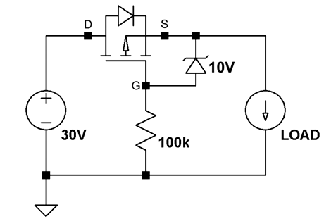
The schematic above shows the P-FET on the high side of the circuit. The gate is hooked to ground, allowing current to move across the DS junction when the battery is connected. This design also uses a clamping diode to keep the gate voltage within a safe range. But there are P-FETs out there that wouldn’t need that diode or resistor. This method wastes ten times less power than a simple diode would have.
We’ve embedded the video after the break where [Afroman] shares the math and reasoning behind his component choices.
[youtube=http://www.youtube.com/watch?v=IrB-FPcv1Dc&w=470]


Excellent video! Thanks.
What would be the right Power dissipation to consider in a circuit with P-Mosfet for reverse polarity protection if the input voltage is 36V and the output will be +12V@5Amps,60W.
Thanks,
Mari
A P-channel MOSFET conduct current from source to drain only. The physical construction will not allow to conduct the P type mosfet in reverse direction (that is drain to source). Anyone clarify this please ?
As long as you maintain the proper Vgs (N-Channel) or -Vgs (P-Channel), the FET will act like a resistor, allowing current to flow both ways.
Thank you for the reply. My understanding was for JFET the your statement is valid. But for Enhancement type P-MOSFET will it still valid?
A relay may be more expensive than a mosfet, but this has no drop:
http://www.edn.com/article/519663-Simple_reverse_polarity_protection_circuit_has_no_voltage_drop.php
No drop but the relay needs to be energized in order to operate.
Efficiency is the goal here.
And beware of relays, they don’t switch immediately so you could submit your load to repetitive power pulses. Could be harmful.
“4. The relay contact resistance is not equal to zero and is dependent of relay design and could be in range from 5-10mOhms for high power relays and up to 0.25 Ohm or higher for reed relays, so it could be comparable with MOSFET Ron resistance.”
Also, I wouldn’t connect the circuit with the Normally Closed contacts as that circuit shows. They are rated for less current than the N.O. contacts and the terminals could weld closed if you have a short circuit on your output load.
You can also buy lower Rds P-channel MOSFETs, if you need. 1/10W on a TO-220 package won’t require a heatsink. The MOSFET is a good approach, and I use it in my circuits already.
You can also put another P-channel MOSFET of the same type the correct way, after the reverse polarity P-ch MOSFET to act as your switch, assuming you don’t want power on all of the time ;-) Just hook the Sources together, and a resistor from each gate to a common node, a zener from connector sources to the common node, and another resistor from the common node to your control circuit that pulls to GND.
Nicely done video!
Nice idea as well… :)
mosfet definitely looks a lot more reliable than the relay implementation
i love these videos
But how about esd?… I think that putting a mosfet there, where people can touch them can easily result in the mosfet being distroyed due to electrostatic discharges… Is that correct?
I use this protection method on the OctoBar LED controller, since I didn’t want the drop and heat of a diode at 3A: http://macetech.com/store/index.php?main_page=product_info&cPath=1&products_id=35
You can see it near the green terminal at the top left corner of the PCB.
Even a Schottky diode would have to dissipate 1-1.5 watts…the PMOS doesn’t even get warm. I don’t use the resistor or zener shown above, since 30V is enough for my application. Here’s the PMOS I’m using…around the same price as a diode with comparable current specs: http://search.digikey.com/us/en/products/AO4435/785-1030-1-ND/1855972
Very useful! Thanks :-)
clever, useful if your in a pinch and have no diodes and loads of fets and need to stop accidental misconnection.
However, I perfer using a fuse rated to the loads requirements and place a diode, reversed across the load after the fuse.
battery wrong way? diode shorts battery through fuse, fuse blows, circuit saved, albeit slight stress on battery and diode for a second or so.
I do the same but use a PTC resettable fuse, that way nothing has to be replaced :)
Btw. sorry, clicked “Report comment” button, I think there should be a confirmation for that to ease the task of the moderators.
I believe that’s called a “crowbar” circuit. It’s particularly important with mobile radios (such as ham radios) that get unplugged and plugged back in on a regular basis. I’ve been doing it that way for years and never had a problem with it. Fuses and diodes are cheap enough, especially compared to replacing the equipment behind them in the circuit.
try bridge rectifier diode
Is this fuse & diode method fast enough to protect things like micro-controllers and FPGAs, though? IME, fuses take a while to blow (relatively speaking), and there is often significant disparity between the rating stamped on the fuse and the actual point at which it might blow. Almost every fuse made has a data sheet with a current vs. time-to-blow (heh) graph, and those are usually just approximations. I’m wondering what you guys may have seen or experienced with these more delicate circuit components I’ve mentioned, and using this type of crowbar. Even with a diode to re-route the current, there might still be enough forward voltage drop, and time until the fuse actually blows, to cause damage, at least in my head. :3
A pair of Schottky diodes with less than 0.5V forward drop, 30V reverse, and ~10ns recovery is working ‘okay’ for most of my applications, but it’s NOT acting as a crowbar; my embedded automotive parts have paralleled Schottky diodes right at the power input terminals.
I really do like this P-FET solution, though. I’m always looking to increase efficiency, and better ways to ‘stupid-proof’ my designs. And by stupid-proof, I mean against myself doing something dumb. And that happens quite often. I should buy Littelfuse stock….
Thanks for sharing, Mike and Afroman!
Sorry, I was still typing while you were posting.
In a word, “maybe”. But also, “maybe not”. See my post below.
Generally, fuses do not blow fast enough, for sensitive circuits. You need something else. Most of them, like circuit breakers, are based on the formula (Isquared)t (t being time).
(there’s a bit more to it than that, switch settings, ratings etc… but it’s refereed to as IsquaredT, the time decreasing with the square of the current)
In fact, they’re meant NOT to blow. The idea being, if you have a circuit overload, the fuse can “handle it” for short periods of time, so the circuit keeps working. The overload goes away, and everything turns back to normal, no intervention required.
That’s why the formula, the more “overload”, the faster the fuse/breaker blows.
I used to help design the computer control, for industrial circuit breakers (200A to 4000A). And even with our “instantaneous” circuit (which may or may not involve the computer), it still took a few tenths of a millisecond to begin to open the contacts.
If you look at the ratings for a “fast blow” fuse, you’ll see they’re normally, not all that fast. They’re only “fast” compared to the noraml “slo-blo” types.
The resettable fuse (PTC) is better, since it’s more proportional (the more current, the more it heats up, the more resistant, which limits the current… and on and on) until equilibrium is reached somewhere.
This FET is a very clever circuit. I wouldn’t say it’s to be used “in a pinch”, it’s to be designed into your circuit. In a pinch, if you only want to stop a revered connection, you’d use a single diode (or a bridge).
It’s main advantage, is eliminating that diode drop. Think, very low drop out regulator, battery powered applications. When you need the maximum from your circuit, without using a DC/DC converter.
A fuse is plenty fast- it primarily serves to keep the diode from blowing up. The diode will let a bit of the negative voltage through, but that is limited by the capacitance of the diode- generally way too little energy to cause damage. By itself, the voltage across the diode will be pretty small, probably less than a volt- until the fuse blows. I often use a current limited wall wart and no fuse- the diode may get hot, but a 1N400x usually has a higher current rating than the supplies I use, so I don’t have to worry about replacing a fuse. Using a FET is handy, but the method presented is relatively expensive in terms of parts and complexity- my real preference is to use a polarized connector on the supply, and maybe a diode across the power inputs that I can not populate once I get the design beyong the “hooking it up with alligator clips” stage.
Just so I understand for myself, and possibly to aid others, this is what you’re suggesting?
Not quite- swap the positions of the fuse and diode (diode arrow pointing up) and connect the V+ to the top of the diode. Reverse the polarity of the battery, and the diode conducts and the fuse blows.
The fuse must be properly sized, though. If the battery (or power supply) is a small (like a coin cell) and the fuse is large, it might never put enough current through to blow the fuse.
This looks like a bad idea to me unless I am remembering incorrectly. I agree the power mosfet will turn on nicely when forward bias. I do remember that they have what works out like a reverse “body diode” that will conduct if its powered up reversed.
http://en.wikipedia.org/wiki/Power_MOSFET#Body_diode
The body diode is already drawn into the schematic though and accounted for. It’s reverse biased when you reverse-polarity.
Also here’s what reads to be an N-channel Mosfet equivalent. http://pages.interlog.com/~speff/usefulinfo/60439565.gif
Hum…
I usually use a Schottky diode in parallel with the source.
The voltage drop across the load is about 0.2~0.4V in reverse.
Logic families such as 74xx have their absolute maximum close Schottky drop.
>However, I perfer using a fuse rated to the loads >requirements and place a diode, reversed across >the load after the fuse.
Much better idea. The power wasted in the diode is very small in case of reverse connection, since the voltage drops quickly. The FET-solution works, but it is not resistant against high voltages, which might occur if there is a long cable with bad contact involved or the like. That is a serious problem, why I would be hesitant to use the FET way in any other solution than directly battery powered devices.
FWIW, an NFET variant is used in some telecom equipment where a ‘large’ value gate resistor also provides inrush current limiting per EN300132-3. In this case its use is in equipment without redundant battery feeds.
Neat idea. I choose to eliminate the whole issue by simply putting a diode bridge on the power input. Then the polarity of the source doesn’t matter.
Of course, as mentioned with high current, this does have power and heat implications. In that situation other cures are probably better.
A diode bridge is a nice solution, but be very careful if your device is wired to anything else- with a bridge you’re changing the ground reference. I would only use this solution if the device is completely stand-alone.
I’ve been using this circuit on a lot of my projects for reverse polarity protection. This is very useful for higher currents compared to a diode, no problem passing 15amps with minimal heat sinking.
“..for the sake of simplicity, you can just use Ron MAX..”
Please do not simply just use the Ron MAX. It’s not the worst case Ron. Look for the drain current or Ron versus Vgs graph.
With a 5.2V input, Vgs would be at 4.5V. Current beyond 1.7A would purely be sourced through the body diode(0.7V drop). This massive part has a large diode that can handle the current. A smaller FET might not. Additionally the turn on time is dictated by the Vgs. Most ICs have a minimum turn on time this might violate if using low input voltages.
You really should have a minimum of 6Vish on the input if you want 2A with this circuit. Using a smaller FET would require a higher Vgs and/or lower currents.
It’s also worth noting that this comparison wasn’t truly fair. A large, expensive FET was compared to a small, cheap Schottky. As Schottky size increases, the voltage drop for a given current decreases. As a FET size decreases, Ron increases. If they were a similar size the difference would be minor and an order of magnitude more expensive. In real products this circuit is only used when voltages are high and currents are large. Why not just use an N-channel?
oh, FYI
This is gonna be helpful as I’m design a piece of field kit with 2 cr2032 cells.
cheers Afroman
Just make sure that 6V is enough for the FET to turn on fully, in fact, you should probably make that 5V if you want to be able to drain the batteries completely.
You can do reverse voltage protection with no power loss more simply with 2 mos-fets arranged in the right way.
Hi Mike,
We need Voltage Source for our application. According to your circuit, if I understand thing correctly, the MOSFET will provide constant current, it will act like Current Source, fix current all the time. However, we need Voltage Source, NOT Current Source. Please advise!
Thanks,
Tony Nguyen
Tony, the circuit above is only a reverse polarity switch, gating off current and voltage. It does not act as a constant current source.
Do you need a regulated voltage source? Just put a voltage regulator between the reverse polarity mosfet and the load.
Battery supplied, voltage regulated (+5V DC @ max 1.5A).
For reverse polarity protection, would a P-MOSFET with cont drain current @ 2A, Vds 30V and Vgs Max 20V be suitable.
It dissipates approx 0.5W, 80m ohm resistance typical.
I think most questions will be answered in Maxims Application note AN636. I’m sure that it is not the first description of this technique because I found this circuit in much older books but it would be nice to state the sources used so others could read them on their own. The mentioned application note answers the more important question on how to work with lower voltages where Vgs wouldn’t be sufficient enough to drive the mosfet into saturation.
Hi, could I use this circuit to protect lithium ion battery from over discharge? ( if I use ZD for let say 3 volts)
something like this circuit
https://sites.google.com/site/varimepodomacky/electronics
This is actually part of Sparkfuns ESP32 lipo circuit lol
question about your circuit – is drain and source wired correctly?
How Would you use an N channel MOSFET to serve as a battery reverse protection please.
Thanks,
John.
http://rs20.mine.nu/w/2013/02/using-mosfets-as-blocking-diodes-reverse-polarity-protection/
I hope this will help you
Is it possible to use this method to stop a battery feeding back through a DC Dynamo (generator) when the Dynamo isn’t running?
I am a beginner. So lets say if i select a 10V zener diode. How do i calculate the current rating of the zener diode.
It doesn’t matter – the zener is only there to limit the gate-source voltage of the MOSFET, and will pass only a small current thanks to the resistor. (The resistor value is chosen such that this current is a few hundred microamps – have a look at the I-V curve for a zener to see why.)
Just tried this circuit out using a SQP100P06-9M3L (Vds 60V, Rds 0.0072ohm, Vgs 2v) and the circuit works just fine. I’ll give it more ‘shock’ testing it this evening, i.e. blast it with a 30V no-holds-barred in reverse and see what the output looks like on an oscilloscope. In terms of doing that with a 1 amp load attached, there’s not even a twitch. The claimed leakage on this device is uAmps, so that shouldn’t be a problem. Dragging 2 amps though the circuit at 12 volts (correct polarity) and the TO-220 package, with no heatsink, wasn’t getting above ambient. In practice I’ll add a baby heatsink, because I have some kicking around, but I’m very impressed that such a simple circuit works so well.
A great tutorial, Mike, with a very clear and concise run-through of the circuit operation.
Thanks :-)