Do You Trust Your Cheap Fuses?

When a fuse is fitted in a power rail, it gives the peace of mind that the circuit is protected. But in the case of some cheap unbranded fuses of the type that come in kits from the usual online suppliers that trust can be illusory, as they fail to meet the required specification.

[Andreas Spiess] has used just these fuses for protection for years as no doubt have many of you, so it was something of a shock for him to discover that sometimes they don’t make the grade. He’s taken a look at the issue for himself, and come up with an accessible way to test your fuses if you have any of those cheap ones.

It’s an interesting journey into the way fuses work, as we’re reminded that the value written on the fuse isn’t the current at which it blows but the maximum it’s intended to take. The specification for fuses should have a graph showing how quickly one should blow at what currents above that level, and the worry was that this time would be simply too long for the cheap ones.

In the video below the break, he looks at the various set-ups required to test a fuse, and instead of a bank of large power supplies, he came up with a circuit involving an 18650 cell and three one ohm resistors in parallel. The resulting 1/3 ohm resistor should pass in the region of 10 A when connected across the 18650, so with a 5 A fuse in that circuit and a storage ‘scope he’s able to quickly test a few candidates. He found that the cheap fuses he had were slower to blow than a Bosch part but weren’t as worrisome as he’d at first thought. If you have any of these parts, maybe you should take a look at them too?

Continue reading “Do You Trust Your Cheap Fuses?”

Copy And Paste Lithium Battery Protection

Lithium batteries have, nearly single-handedly, ushered in the era of the electric car, as well as battery energy storage of grid power and plenty of other technological advances not possible with older battery chemistries. There’s just one major downside: these lithium cells can be extremely finicky. If you’re adding one to your own project you’ll have to be extremely careful to treat them exactly how they are designed to be treated using something like this boilerplate battery protection circuit created by [DIY GUY Chris].

The circuit is based around the TP4056 integrated circuit, which handles the charging of a single lithium cell — in this design using supplied power from a USB port. The circuit is able to charge a cell based on the cell’s current charge state, temperature, and a model of the cell. It’s also paired with a DW01A chip which protects the cell from various undesirable conditions such as over-current, overcharge, and over-voltage.

The best thing about this design isn’t the design itself, but that [DIY GUY Chris] built the circuit schematic specifically to be easily copied into PCB designs for other projects, which means that lithium batteries can more easily be integrated directly into his other builds. Be sure to check out our primer on how to deal with lithium batteries before trying one of your own designs, though.

Continue reading “Copy And Paste Lithium Battery Protection”

Protect Your Batteries Before You Wreck Your Batteries

[Jan] is solving a problem many of us have had, deeply discharging our project’s batteries and potentially damaging the cells.

His board can handle batteries from 6 to 34 volts and supports both LiPo or Lion batteries. The board can be flexible about its cut-off voltage. It also has a feature we really like; the user can set a delay before it shuts off the battery: useful in cases where a heavy peak current draw causes the battery to operate at a lower-than-threshold voltage for a few seconds. Once the board is shut down it takes a manual reset to allow power to be drawn again.

His latest iteration of the board is an impressive 1 sq. inch in size! This can fit in just about any project and it’s even flexible in the choice of battery connector. Next time we have a high current draw project with expensive batteries or maybe a monitoring device that’s expected to run a long time we may throw one of these boards in there just to be safe.

Repurposed Plastic Protects PCBs

An errant wire snipping across the wrong electrical pins spells the release of 
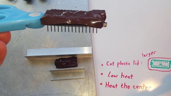
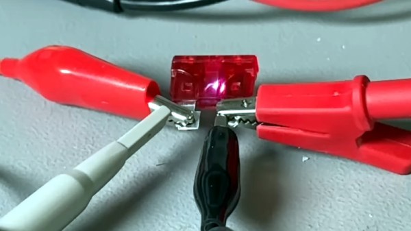
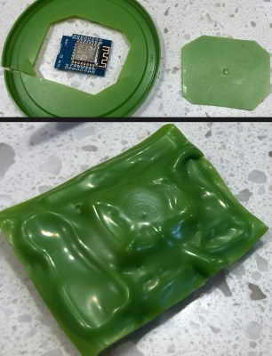
your magic smoke. Even if you are lucky, stray parts are the root of boundless malfunctions from disruptive to deadly. [TheRainHarvester] shares his trick for covering an Arduino Nano with some scrap plastic most of us have sitting in the recycling bin. The video is also after the break. He calls this potting, but we would argue it is a custom-made cover.

The hack is to cut a bit of plastic from food container lids, often HDPE or plastic #2. Trim a piece of it a tad larger than your unprotected board, and find a way to hold it in place so you can blast it with a heat gun. When we try this at one of our Hackaday remote labs and apply a dab of hot glue between the board and some green plastic it works well. The video suggests a metal jig which would be logical when making more than one. YouTube commenter and tip submitter [Keith o] suggests a vacuum former for a tighter fit, and we wouldn’t mind seeing custom window cutouts for access to critical board segments such as DIP switches or trimmers.

We understand why shorted wires are a problem, especially when you daisy-chain three power supplies as happened in one of [TheRainHarvester]’s previous videos.

Continue reading “Repurposed Plastic Protects PCBs”

ATtiny Chip Abused In RFID Application

One of Atmel’s smallest microcontrollers, the ATtiny, is among the most inexpensive and reliable chips around for small applications. It’s also one of the most popular. If you don’t need more than a few inputs or outputs, there’s nothing better. As a show of its ability to thrive under adverse conditions, [Trammell Hudson] was able to shoehorn an ATtiny into an RFID circuit in a way that tests the limits of the chip design.

The RFID circuit only uses two of the ATtiny’s pins and neither of which is the ground or power pin. The ATtiny is equipped with protective diodes on its input pins, and if you apply an AC waveform to the input pins, the chip is able to use the leakage current to power itself. Once that little hurdle is crossed, the ATtiny can do the rest of its job handling the RFID circuitry.

This project takes a deep dive into the internals of the ATtiny. If you’ve ever wondered what was going on inside of everyone’s favorite tiny microcontroller, or if you’re looking for an RFID circuit that keeps parts counts to an absolute minimum, this is the project for you.  The ATtiny is more than just a rugged, well-designed chip, though. It’s capable of a lot more than such a small chip should be able to.

Thanks to [adnidor] for the tip!

What Does ESD Do To My Circuit And How Can I Protect Against It?

[Kevin Darrah] is risking the nerves on his index finger to learn about ESD protection. Armed with a white pair of socks, a microfiber couch, and a nylon carpet, like a wizard from a book he summons electricity from his very hands (after a shuffle around the house). His energy focused on a sacrificial 2N7000 small signal MOSFET.

So what happens to a circuit when you shock it? Does it instantly die in a dramatic movie fashion: smoke billowing towards the roof, sirens in the distance? [Kevin] set up a simple circuit to show the truth. It’s got a button, a MOSFET, an LED, and some vitamins. When you press the button the light turns off.

He shuffles a bit, and with a mini thunderclap, electrocutes the MOSFET. After the discharge the MOSFET doesn’t turn the light off all the way. A shocking development.

So how does one protect against these dark energies out to destroy a circuit. Energies that can seemingly be summoned by anyone with a Walmart gift card? How does someone clamp down on this evil?

[Kevin] shows us how two diodes and a resistor can be used to shunt the high voltage from the electrostatic discharge away from the sensitive components. He also experimentally verifies and elucidates on the purpose of each. The resistor does nothing by itself, it’s there to protect the diodes. The diodes are there to protect the MOSFET.

In the end he had a circuit that could withstand the most vigorous shuffling, cotton socks against nylon carpeting, across his floor. It could withstand the mighty electric charge that only a grown man jumping on his couch can summon. Powerful magics indeed. Video after the break.

Continue reading “What Does ESD Do To My Circuit And How Can I Protect Against It?”

Reverse Voltage Protection With A P-FET

[Afroman’s] latest video shows you how to add reverse voltage protection with minimal power loss. At some point, one of your electronic concoctions will turn out to be very useful. You want to make sure that a battery plugged in the wrong way, or a polarity mistake with your bench PSU doesn’t damage that hardware. It’s easy enough to plop in a diode for protection, but as [Afroman] points out, that wastes power in the form of heat when the circuit is working correctly. His solution is to add a P channel MOSFET which only allows power to flow when the polarity of the source voltage is correct.

The schematic above shows the P-FET on the high side of the circuit. The gate is hooked to ground, allowing current to move across the DS junction when the battery is connected. This design also uses a clamping diode to keep the gate voltage within a safe range. But there are P-FETs out there that wouldn’t need that diode or resistor. This method wastes ten times less power than a simple diode would have.

We’ve embedded the video after the break where [Afroman] shares the math and reasoning behind his component choices.

Continue reading “Reverse Voltage Protection With A P-FET”