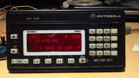
[PRC148] picked up a Motorola Micom radio from eBay. These are US State Department surplus, but apparently the 125 Watt HF units are top-of-the-line at a tenth of the sticker price. The one hangup is that they’re headless; you can’t control them without additional hardware. But the Internets are often kind to the hobbyists, and this is no exception. You can get software to run the radio from a PC thanks to the Micom Yahoo Group. [PRC148] took that software as an example and built his own stand-alone interface. [Cached version of the page]
The head unit is an Arduino driving a four-line LCD display and a rather large array of buttons. The forum thread linked above shows his humble beginnings on a breadboard. During the project [PRC148] learned a lot of skills to end up with what you see above. Hiding behind the reused bezel is a PCB he designed in Eagle CAD and etched himself. It allowed him to cram the tactile switches close enough to work with the button overlay on this keypad.
UPDATE: The traffic from this feature took down the forum hosting the content. They requested that we do not link to them because of this. A cached version without images can be found above thanks to [Termm].


Bravo!
Damn!
Congrats man, Seriously big Kudos!
I wish I had the skills to do that, lol.
Seems cool but looks like there are too much visitors on his website : “This Account Has Been Suspended” :(
Google cache of the page here (without images):
http://webcache.googleusercontent.com/search?q=cache:vIlDTn0TGTMJ:www.p25.ca/archive/index.php/t-399.html
I wish you had picked up this story when it was a little fresher in May as it seems there are no more bargain $150-$200 Motorola Micom radios on eBay… Bummer!!!
I was just going to post this same thing. I’d stared and stared at those Micom’s saying “Man those are beastly HF rigs, too bad they don’t have the control head”… but I didn’t do any further research. Hindsight being 20/20, I’ve watched several of these go by on ebay for under $100, but they appear to have pretty much dried up.
I don’t know who David is but this is Casey, the person that actually designed and built this project. I am happy to answer questions but please provide cred to forum user mancow who is me (Casey).
fixed! that happens sometimes. David tipped us off to the story and Mike must have just overlooked the “not my project” part. Sorry.
No worries. I haven’t been to this site all that much so I wasn’t familiar with the process of how things work.
It was originally build on a regular Arduino, then I went to the Mega board but that was too big to use inside the housing. It presently uses a mini Arduino board I got off ebay for $15. The housing is a Motorola A9/W9/X9000 style that has been gutted and the front cut out. The panel is clear Lexan from HomeDepot. I dremeled out the buttons holes and used buttons from a Motorola Spectra radio head. The F buttons are Moto buttons that were sanded down to remove the icons. I printed the characters to clear mailing labels then used some varnish over them. The panel inlay is printable inkjet vinyl with 10 mil Lexan frosted laminate that was applied with a GBC laminator. There are still a few bugs but for the most part it works just like the factory head. I am now working on the audio interface and hoping to get it finished soon. Thanks to everyone for the kind words.
Casey
It has been a year since you made the head. What is new on the project. It would be nice if you could offer a kit for all of us who have ourchased these rigs and are in high need of a control head. Are you planing to offer control head kits after you get all the bugs out of your system. Thanks,
Joe Foss
Battle Creek, MI
Oh and sorry, I meant to say I’m PRC148 on that board, not mancow. I go by mancow on others. I guess there are too many to keep track of at times.
I hope that eliminates any confusion.
I too noticed the surplus supply has dried up a bit. Hopefully some more will surface one of these days.