Late last September, Hackaday along with other hackerspaces including North Street Labs, 1.21 Jigawatts, Maker Twins, made their way to the NYC Maker Faire via the Red Bull Creation contest. The objectives of the contest were simple: build a game in 72 hours, have people vote on it, and join the Red Bull crew in Queens for a carnival-like atmosphere.
When the Maker Faire was over, Red Bull had some leftover props from their Midway at Maker Faire setup, including a few illuminated carnival signs. Without any use for them, they graciously gave Hackaday, North Street, Maker Twins and the Jigawatts the signs to their respective rides.
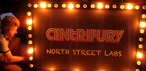
Now that things have settled down and the rides have returned to their home base, the folks over at North Street decided to improve their sign. At Maker Fair, these signs were illuminated by 50 incandescent bulbs, all wired on the same circuit. [Steve] over at North Street had the awesome idea of adding a persistence of vision aspect to the sign, so work began on wiring every fourth bulb in series.
To drive the light circuits, North Street repurposed the Arduino Relay shield originally used for the lights on the Centrifury, their competitive centrifuge and spinning hell of a game. In the video after the break, you can see the addition of POV lights really brings out the carnival atmosphere. A literally brilliant build, and a wonderful addition to the scariest game ever made.
[youtube=https://www.youtube.com/watch?v=uyM3Mzg3gkA&w=470]


Nice improvement, but wouldn’t you have wired every 4th bulb in parallel?
Yeah, you’re right. We were up extremely late making this thing. I was thinking “sequence” but saying series the whole time. I shouldn’t have used ambiguous language that means something else in electronics. When one bulb is removed, the rest stay lit. It’s definitely parallel (done in sequences of 4). I fixed the website and added annotation to the video.
Nice except that I can’t see it being called a POV unless the channels were multiplexed. Otherwise it is just a 4-channel driver.
I can see the relay board being used as a quick solution especially if it is only illuminated on occasion, but if it was used daily I would have suggested solid-state relays or transistors. Having PWM channels could have given cool dimming effects.
Yeah, those relays are eventually going to wear out. But if that’s all they had handy, they wil probably last for years.
I like SSRs, especially the DIN rail kind that come with indicator LEDs so you can tell when they’re active. Makes debugging much easier (but boy, are they expensive unless you can find them used)
POV? You keep using that word. I do not think it means what you think it means.
Persistence Of Vision? In what way? I don’t think they know what that means.
Series? They are likely wrong about that, too, unless they are using low voltage bulbs.
Parallel, definitely parallel.
And it’s usually called a “light chaser” display, I think.
I just addressed the wiring confusion in the video/site. We were looking for a better term to describe the motion, but we didn’t find any wiki pages for it. You literally track a single bulb, and it appears to travel around the sign, so that was the best term I could use to describe the effect at the time.
They wired the bottom wrong.
The number of total bulbs divided by 4 isn’t a whole number.
You are right – I played it slow and the pattern on the bottom is screwy. Or perhaps my vision doesn’t ‘persist’ the way that theirs does.
There were 2 swapped wires on the base. Steve announces it in the video since it was our first time firing it up. It says so on our website, as well as the description of the video. We fixed it the next morning.
After fixing it, the uneven bulb issue (50/4) is still there on certain effects but barely noticeable unless you’re staring at the very bottom left corner.
I used to build something similar using binary counters and solid state relays to control the lights. A friend in the theater business said the sequence is called a ‘Chase’ .