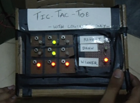
Here’s another entry in the 7400 Logic contest. [Circuitchef] used gates and a few flip-flops to build a two-player electronic Tic-Tac-Toe game. The full details or shared in the PDF file he links to in his post. We’ve also linked to it after the break in case the Dropbox he is using becomes unavailable.
He provides a nice block diagram which helps to understand the game’s design. The board is arranged in a 3×3 matrix of momentary push buttons and bi-color LEDs. Each player takes turns pushing the button in the square they’d like to claim. The input circuitry uses flip-flops to establish which player’s turn it is, illuminating the appropriate color for that square. A set of 3-input AND gates monitor all possible combinations of winning patterns. The outputs of those gates are OR’d down to just one output which is used to light up the ‘Winner’ LED with the right color. If all boxes are lit up and none of those combinations is satisfied the game is declared a draw. This can all be seen in the demo embedded below the fold.
Project Design Details (PDF)


very cool. what happens if both players press the same button?
guess I should read first. haha
I think if one button is clicked then the same button is not clickable again until a winning condition is reached or all the lights in the board are lit.
Bravo!
Brilliant logic chip project. The tape and cardboard enclosure reminds me of my earliest dabbling a with electronics projects as well.
Nice! Will be fun to build for an X-mas present for my kids.
Awesome….
Once in school I had to code tic-tac-toe in C#. Really cool that someone did that “in real”.
But don’t try to board a plane with that. The TSA’s gonna shoot you on sight.
Sir, I am a student you said you used 30 ICs right? exctly 30 ICs?? i used 31. the switch design is used 9 times?? so that it requires a lot of ICs, am i right?
What is the voltage source used here?
What goes into the reset of each flip flop? is it a ground? HELP ASAP
can i get circuit diagram?? link is expired..