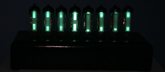
If Nixies aren’t cool enough, maybe it’s time to step it up to magic eye tubes.
Magic eye tubes are, like Nixies and Dekatrons, display tubes. Unlike the alphanumeric characters of Nixies or rotating points of light in a Dekatron, Magic eye tubes are either bar graph or ‘Pac-Man’ displays that were used to show the signal strength of a radio station on very expensive radio sets.
After doing a few experiments with tubes, [sylvain] thought it would be cool to do something with magic eye tubes. He sourced eight vertical ‘bar graph’ magic eye tubes and built an audio spectrum analyzer.
One of the more difficult things to do was to compute the power levels for each frequency band. There are a few graphic equalizer ICs available, but [sylvian] decided to go the old-school, harder way by putting an FFT algorithm on an ATMega624.
An impressive piece of work that would look amazing next to a nice tube stereo system.


Old school easy way would be to use a bandpass filter for each tube. No uC needed :)
Yeah, I think new school is to do everything with a microcontroller :p
That’s exactly what I thought.
proper oldskool way would have been the easier way. – analogue electronics.
Yes, like taking a channel from an old graphic EQ. They already have the filter banks, and the sliders just mix the sound together again. EQs with broken sliders are easy to come by at swap meets.
Am I the only one that thought the title referred to stereograms? http://en.wikipedia.org/wiki/Autostereogram
I kept trying to unfocus my eyes and “see” the hidden spectrum.
No. :)
Neat, I didn’t know these tubes came in a linear(?) variety. I’ve only ever seen the circular kind.
They look like EM84 magic eye valves, just like the ones I remember from the 1970s in reel-to-reel tape recorders.
Oh darn. I was so proud when I finished my stereo VU meter with EM84 tubes: http://www.youtube.com/watch?v=TIVUGsvTpVE
Not what I was expecting when I read spectrum analyzer, although it had me wondering hoe magic eye displays could be used as a spectrum analyzer. Something that display all the radio frequencies in a sample & their relative power level
just need some bandpass filters and few analog electronics to call it oldskool… there tubes with uC ?! Overall, this cool, but it is disappointing to see a micro-controller, instead of the real deal analog. Whats wrong with analog? Seriously…. had to overclock the controller to make it work? That made me LOL. To each there own…
Agree. Shouldn’t have a micro and it should use all analog electronics.
@sylvain
i love the look, it’s slick
the fact that you did NOT put LEDs under
the tubes makes it look BETTER!
you SHOULD get a greenish glow
reflecting off of the case.
these tubes arent all that bright
and LEDs always drown em out.
good job of letting the tubes do the lighting! :)
PS:
i agree with everyone else on the TYPO.
im pretty sure H.A.D. meant …”decided to go the NEW-school”…
could have been just simple capacitors, inductors, and resistors,
all calculated with:
Xc=1/(2pifc)
XL=2pifL
BW=Xc/RW (or is it BW=RW/Xc ?)
and make it a double(pie) filter
its still a good result though, theres nothing wrong with a uC.
and yes these DID exist back in 1940, …
they used them to help design stuff.
they just costed about 20,000$ in today’s money
and were as large as a suitcase and heavy.
have pictures of one from 1940? you’r lucky. please post for all to see!!!