We’re used to low cost parts and a diversity of electronic functions to choose from in our projects, to the extent that our antecedents would be green with envy. Back when tubes were king, electronics was a much more expensive pursuit with new parts, so designers had to be much more clever in their work. [Thomas Scherrer OZ2CPU] has just such a design on his bench, it’s a Heathkit Capaci-Tester designed in 1959, and we love it for the clever tricks it uses.
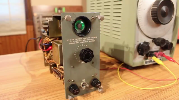
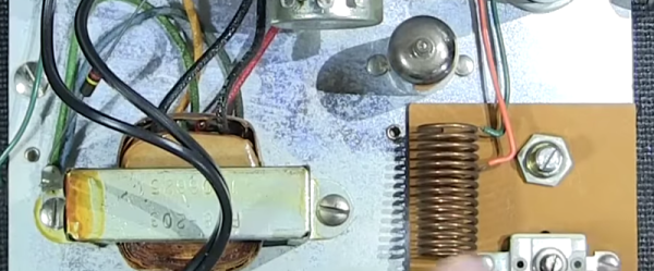
It’s typical of Heathkits of this era, with a sturdy chassis and components mounted on tag strips. As the name suggests, it’s a capacitor tester, and it uses a magic eye tube as its display. It’s looking for short circuits, open circuits, and low equivalent resistance, and it achieves this by looking at the loading the device under test places on a 19 MHz oscillator. But here comes that economy of parts; there’s no rectifier so the circuit runs on an AC HT voltage from a transformer, and that magic eye tube performs the task of oscillator as well as display.
He finds it to be in good condition in the video below the break, though he removes a capacitor placed from one of the mains input lines to chassis. It runs, and confirms his test capacitor is still good. It can’t measure the capacitance, but we’re guessing the resourceful engineer would also have constructed a bridge for that.
Continue reading “A Magic Eye Tube Does All The Work In This Kit”