Sure, the physical build itself looks great, but it’s what [Michael] did with the firmware that impresses us the most. He’s using an Arduino Mega to drive the 7x7x7 cube and manages to squeeze out what he calls 142 frames per second with the setup. We’re not sure FPS is the right measurement, as we believe it’s the multiplexing rate that he’s trying to describle. It takes 144 uS to scan the entire matrix once. He performs the scan seven times per frame and the result is a flicker-free appearance, even to cameras.
You can see a video demonstration after the break. Since [Michael] emailed us directly with more details about the build we’ve pasted those below the fold as well.
If you’re looking for a more entry-level Arduino LED cube this 4x4x4 project is just the thing.
https://www.youtube.com/watch?v=CKCjsbNEUUE
The cube is able to process 142 frames per second, that is, 1 frame every 7 milliseconds. Within this time period, it loops through a still frame 7 times (Each cycle of POV lasts 144 microseconds). This is able to compensate for flickering during video recording, allowing all camera’s to record fluid video without distortion.
The cube itself is controlled with an Arduino Mega 2560. For each frame in memory, the Arduino reads and bit shifts 49 bytes of data for an encoded duration. This allows for the cube to be applied to a variety of purposes, from text display to effects to music visualisation.
The frames were generated through complex Processing scripts, allowing for a multitude of operations such as shifting in any direction (seen in the rain effect), and an edge shift (seen in the scrolling text around the outside of the cube). These scripts were used to perform the basis of calculations for fireworks, as well as sine waves in 1, 2 & 3 dimensions (seen in the video).
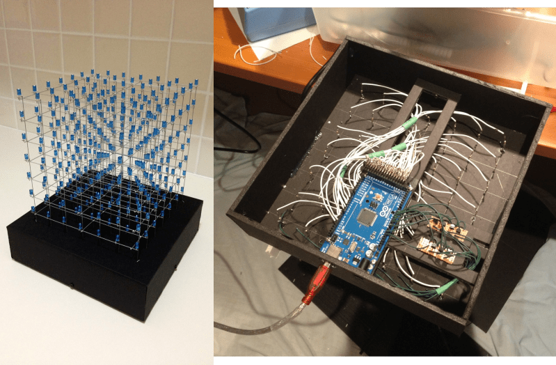
In this cube the supporting structure was made 0.9 mm galvanised steel wire, straightened by stretching the wire. The 5mm Blue LED’s are positioned 30mm apart, with the anodes being attached to the verticals (white wires in the image below) & the cathodes are attached to the horizontal layers (green wires in the image below – bottom right – shown passing through NPN transistors). The Arduino Mega 2560 R3 is positioned on a suspended platform, with the anodes controlled on the Digital Pins as opposed to the cathodes on remapped AnalogInputs.


I couldn’t see how 142fps was ambiguous? seems legit to me. If each frame took 7x144us then he’d have over 1000fps. Obviously it some CPU time is taken up by processing in between each ‘display’ cycle. The display cycle has to be fast otherwise you have no CPU time left over to organize the next frame.
The only thing I would do different is to paint all the solder joints and wire leads black so the light from the LED’S wouldn’t reflect off of them, I think that would make a cleaner display. And use frosted or diffused lens LED.
The only thing I would do different is to drop the music, if you even can call it that.
lol agreed
Agreed too!
Hey 2004 called. It wants your video back.
360p quality, piss poor music. And well, frankly, a piss poor 3d cube.
Sorry, but they’re getting tiresome now. They’ll NEVER be the future of display technology.
The pasted text refers to images, which I guess he sent in? Any chance we could see them?
and what is it, exactly that he did with what that impresess you soo much? Because i can’t seem to find any documentation whatsoever. Could you please make the link to more details more visible, so that stupid people like me can find it?
yeah, paint all the structure etc etc matte black for sure
also, I believe it’s 142 refreshes a second, but clearly it’s only about 20fps.
“It takes 144 uS to scan the entire matrix once.”
144 microsiemens? nice one, szczys
Source?
There is more info here
http://forum.allaboutcircuits.com/showthread.php?t=79876
HAD you should feature youtuber kdarrah1234 for his 8x8x8 LED cube how to vids
He covers how to build it up and program, very detailed
From what I can figure out, each frame takes about 7ms, during this time it switches through all 49 of the led rows once, each of these 49 cycles takes about 144us.
The registration process for this site is REALLY PAINFULL, so I’v tried to get the images to repost on my site so you can all see them but the site wont let me. would anyone with a working account try to access and repost the 2 pics and 2 schematics he has there?
I think what bugs me most about projects like this is that this person learned enough to understand power requirements, resistor use, transistor use, multiplexing, good soldering and the logic coding required to do all the fancy patterns… but they still left their $60 dev board in the project instead of replacing it with the $8 in equivalent parts.
An Arduino is nothing more than a cheap microcontroller (with the Arduino bootloader,) a voltage regulator and a USB programmer on a board. An Arduino can be used to burn the bootloader onto a blank microcontroller and program your sketch onto it, and a 5v wall wart is a cheap voltage regulator (but you can build one for even cheaper.)
Please stop leaving your expensive development boards in your projects!
Actually, I retract $8 part of my statement. He’s using Processing to run the thing over USB, so he’d need to add an FTDI board or a PL2303HX, which would add between $2 to $10 bucks. Still cheaper than leaving a MEGA in there!