Timing is everything and that’s why most communication protocols require a very accurate clock source. The WS2811 LED strip controllers are no different. But [Danny] figured out a way to drive them reliably with an 8MHz clock source.
The WS2811 has become one of the most popular controllers for RGB pixels and strips alike. We’ve seen several hacks used to address them, including the 16MHz AVR technique that inspired [Danny] to take on this project. He planned to use that library but the 25-day shipping time for a 16MHz crystal drove home to invent a way to use the internal oscillator instead.
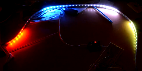
The gist of the hack is that he wrote assembly code to handle pairs of binary bit values. With a code block for each of the four possible combinations in hand he had to find a way to craft the conditional jumps to preserve accurate timing. After hitting the wall trying to solve this puzzle by hand he wrote a C++ program to solve it for home. The proof is in this video which shows one chip driving multiple Larson scanners on a single strip.


That’s a nice writeup.
I’m guessing you probably didn’t realize Adafruit’s Neopixel library already supports WS2811 strips on both 8 & 16 MHz AVR-based Arduino? They use pretty much the same approach. But they didn’t write such a nice wiki page with the technical details….
I also saw your page about parallel output. Just so you know now, the OctoWS2811 library (which I wrote and was mentioned yesterday here on HaD) does this, with nearly zero CPU overhead using the DMA controller on a 32 bit ARM part. OctoWS2811 uses the transposed format you described. My ARM-based code probably won’t help at all on AVR, since there’s no DMA controller… but I did write a nice Processing program to stream video to simultaneously to any number of boards in that transposed format. Even if you don’t do streaming video, that code might help you get some data into the transposed format.
Thanks Paul,
I did see your OctoWS2811, and intend to study it closely.
I was not aware that the Neopixel library also supported 8Mhz, darn they beat me :-)
Actually I believe I have beat both of you :)
I have been working on a lws2812 library for the AVR for a while after I was dissatisfied with the existing solutions. Most implementations rely on contrived c++ template libraries (fastspi lib) or on unrolled loops. Both lead to a large memory footprint. Furthermore, instructions which are not compatible to all AVRs are used often (like MUL or CBI/SBI).
You can find my implementation here: https://github.com/cpldcpu/light_ws2812
Down to 8 MHz all routines are looped with a memory footprint below 50 bytes. As a special bonus, I managed to implement a 4 MHz version, which unfortunately has to rely on loop unrolling.
Yesterday also submitted ws2812 support to little-wire, which allows controlling WS2812 strips via USB on a humble ATTiny85.
http://littlewire.cc/
Experimental v1.2 here:
https://github.com/kehribar/Little-Wire/tree/danger/v1.2
I took a look at the ws2812_sendarray_mask-function under the ws2812_8MHz ifdef. The byte-timing looks correct to me and is indeed nice and compact, the while loop introduces inter-byte delays though and that is outside spec. As [Alan Burlison] wrote in his 16Mhz write-up, that may work on some led strips and fail on others.
Hi,
thank you for your feedback! According to my experiments the critical part of the timing is between the rising and the falling edge. I assume what the controller does is to trigger a monoflop at the rising edge and then samples the input after ~0.5µs. The timing between the falling and the rising edge triggers the reset condition, which seems to happen anywhere between 5µs and 50µs. So that means that there is some tolerance to the timing of the latter part.
It would be easily possible to achieve perfect timing for the 8Mhz version with loop unrolling like in the 4 Mhz version. But that comes at the expense of a lot of code space. So far I have not seen any issue, but I only have tested on short strips so far. Would be interested in feedback if there are any issues.
Achieving perfect timing for the 4Mhz version is near impossible since there is only one cycle per bit left – and at some point you have to do that pesky 2 cycle jump…
I just took a better look Neopixel. [Paint Your Dragon] managed to do the same thing in less code. He just unrolled the bit loop and that’s all, doesn’t really need the extensive write-up, because it’s so simple.
Double-darn you Lady Ada and your genius friends!
(who would have thought that somebody could utter that sentence in the 21th century).
I guess nobody ever told me this was supposed to be difficult. :-)
I had my WS2811s working on an 8MHz ATtiny85 about an hour after my LED strip arrived. No assembly language needed apart from a NOP.
I’m still using the same code today (although it now supports 16MHz as well…)
Demo sketch: http://www.artlum.com/arduino/WS2811_demo.7z
I wrote an assembly language version because I wanted to play back an 8kHz sound sample while updating the LEDs (a bit trickier at 8MHz).
Your bit-timing seems alright, but there’s a huge gap between bits with the “b=b+b”, “if (*b&0x80)…” and “while (–i !=0)” and all. Maybe this works for your LEDs, but the timing is not to spec and this may (and I guess: will) fail for other instances.
[Alan Burlison]’s featured write-up dedicates some text on why you’d want to stay in spec with the timings
AFAIK the datasheet doesn’t say anything about time between bits. The chip looks for a rising edge at the start of a bit and starts counting from there. Time since previous bit doesn’t seem critical. In testing I added a for() loop counting up to 7 between bits and the chip was still happy.
I’ve used this code on long LED strips, some surface mount WS2811s, even a WS2811 in a DIP8 package. It’s always worked.
I agree with this. The chip is almost certainly an asynchronous design that is clocked from the rising edge of datain. So all the babble about “jitter” is prettly useless…
The chip *has* to be able to detect a rising edge and use it to process a bit – it wouldn’t work otherwise because the first bit of the 24 _always_ arrives at an unknown time.
If the chip has that ability then it doesn’t make much sense for it to suddenly apply strict timing to all the subsequent bits. The easiest thing to do is use the same logic as for the first bit.
Neat way of graphing and developing the code, enjoyed seeing it. Though it’s 4x Larson scanners in the demo, with the strip in a semicircle it reminds me of Close Encounters.
25 days for an oscillator?what planet are you on?
His “25 days is a long time” comment was simply witty dry humor. In that context, your sardonic sarcasm is ironically tragic.
Are you the “real” Mike Harrison, or just a pretender?
http://www.theamphour.com/get-your-questions-in-for-mike-harrison-of-mikes-electric-stuff/
Actually, 20-25 days appears to be somewhat of a standard maximum delivery from a Hong Kong seller on ebay to mainland Europe. Normally the goods arrive a lot sooner, but on this occasion it actually took weeks for the oscillators to arrive. Which was a good thing because really, I just needed a good excuse.
But now I have 10 unused oscillators lying around…
25 days? I ordered something from Digikey a couple of months ago, paid for fedex, damn thing spent a month in some sorting facility in Memphis – back to Mouser who at least will ship to New Zealand from Hong Kong, orders arrive in 2-3 days
Hah, who’s sardonic, sarcastic and tragic now? :-)
And then again, my _comment_ about the 25 days _was_ an attempt at witty dry humor.
Now play nice, dears :-)
Huh? I’ve been using these on an 8MHz ATtiny85 since about an hour after I got my first strip, no assembly language needed.
At 800MHz, or 400MHz data steam?
800MHz
Hz*, sorry. You must be using huge unrolled loops if not using ASM…?
The code is here: http://www.artlum.com/arduino/WS2811_demo.7z
No unrolled loops (huge or otherwise) and no ASM needed.
That comment might be about how fast 800 MHz would be, 1000X faster than 800 kHz, or more correctly 800 kbits/sec, which the WS2811 chip requires.
1 bit = 1 Hz. Semantics.
You should look closer at your ws2811.h file…
#define NOP __asm__(“nop\n\t”)
and several uses of your NOP declaration to maintain that timing issue native C tends to run into.
Fungus: What you are doing in ws2812.h is the definition of loop unrolling. You code is huge and may break with any change of compiler conditions. This is a pure hack.
But oh well, look where we are… :)
I can change the “NOP” to “LED_PIN=0” if it will please the pedants … it’s all the same to me.
The only point I was trying to make is that driving a WS2811 with an 8MHz AVR chip isn’t particularly difficult. When it came up here as some sort of miracle it made me raise an eyebrow.
Hahah, no I agree with that
It *IS* a nice optimization though. Those few extra clock cycles might be useful if you’re trying to drive huge strings of LEDs.
This is already done.
And I’ve worked my ass off long and hard to revise the inline assembly as well.
Where were you when I needed you? :(
Ok, not sure whether anybody still cares at this point. BUT: I have updated my light weight WS2812 library. Almost all routines meet datasheet timing specifications now, down to 4 MHz processor clock. Furthermore, I am pretty sure that the library provides
the smallest code size footprint of all available solutions.
Find v0.7 here:
https://github.com/cpldcpu/light_ws2812/tree/master/light_ws2812
I have driven ws2812 with uart at 4Mbps, you can laso use SPI at 3.2Mbps.
I drove the ws2812 from a 8-pin pic, the pic can have a framebuffer of 68 units for 24bit colour and 100leds for 16bit colour, this is with 256 Byte ram, RAM is the only limit.
Hello
I am trying to write a program for pic16f877a that drives WS2812B, i am using a 20 MHz oscillator, can you help me please ?