3d printed tiny gym in a box with mirror and led strip lighting

Get Pumped For This Miniature Gym

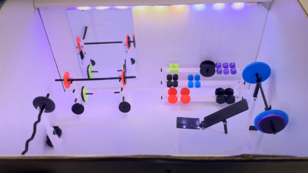
[Duncan McIntyre] lives in the UK but participated in a secret Santa gift exchange for his Dutch friends’ Sinterklaas celebration. In traditional maker fashion, [Duncan] went overboard and created a miniature gym gift box, complete with flashing lights, music and a motorized lid.

[Duncan] used [TanyaAkinora]’s 3D printed tiny gym to outfit the box with tiny equipment, with a tiny mirror added to round out the tiny room. An ATmega328P was used as the main microcontroller to drive the MP3 player module and A4988 stepper motor controller. The stepper motor was attached to a drawer slide via a GT2 timing belt and pulley to actuate the lid. Power is provided through an 18V, 2A power supply with an LM7805 providing power to the ATmega328P and supporting logical elements. As an extra flourish, [Duncan] added some hardware audio signal peak detection, fed from the speaker output, which was then sampled by the ATmega328P to be able to flash the lights in time with the playing music. A micro switch detects when the front miniature door is opened to begin the sequence of lights, song and lid opening.

[Duncan] provides source on GitHub for those curious about the Arduino code and schematics. We’re fans of miniature pieces of ephemera and we’ve featured projects ranging from tiny 3D printed tiny escalators to tiny arcade cabinets.

Video after the break!

Continue reading “Get Pumped For This Miniature Gym”

Rib Cage Lamp Kicks It Up A Notch With Party Mode

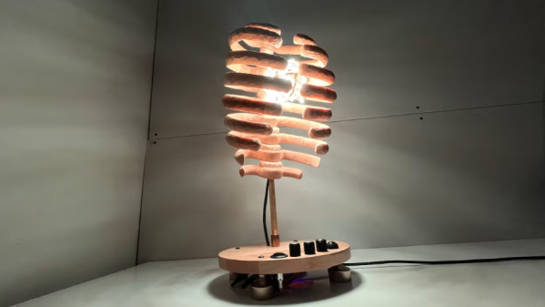
We think [Michelle]’s sound-reactive rib cage lamp turned out great, and the photos and details around how it was made are equally fantastic. The lamp is made of carved and waxed wood, and inside is a bundle of LED lighting capable of a variety of different color palettes and patterns, including the ability to react to sound. Every rib cage should have a party mode, after all.

The LED strip is fashioned into an atom-like structure.

Turns out that designing good rib cage pieces is a bigger challenge than one might think. [Michelle]’s method was to use an anatomical 3D model as reference, tracing each piece so that it could be cut from a flat sheet of wood.

The resulting flat pieces then get assembled into a stack, with each rib pointed downward at a roughly 20 degree angle. This process is a neat hack in itself: instead of drilling holes all at exactly the same angle, [Michelle] simply made the holes twice the diameter of the steel rod they stack on. The result? The pieces angle downward on their own.

The LED lighting is itself a nice piece of work. The basic structure comes from soldered solid-core wire. The RGB LED strip gets wound around that, then reinforced with garden wire. The result is an atomic-looking structure that sits inside the rib cage. An ESP32 development board drives everything with the FastLED library.

Code for everything, including the sound-reactive worky bits, which rely on an INMP441 I2C microphone module is all available on GitHub. And if you want to make your own sound-reactive art, make sure to check out these arms as well.

Want to see the rib cage in action? A short demo video is embedded below that demonstrates the sound reactivity. Equally applicable to either party or relaxation modes, we think.

Continue reading “Rib Cage Lamp Kicks It Up A Notch With Party Mode”

Two Wire Sensors On LED Strips

While addressable LED strips are all the rage, [Mike] from [mikeselectricstuff] has been working on an installation using the more basic two-wire strips that are simply controlled via PWM dimming. He’s recently figured out a tidy way to send sensor signals down these strips without adding any additional cabling.

Schematic for hooking up a sensor
The circuit in question.

The build uses 24 V LED tape, which consists of gangs of 6 LEDs in series with a forward voltage of 3V. Thus, these strips don’t even begin to light until approximately 18V is across them.

By adding a 15 V Zener diode and a resistor across the MOSFET which dims the LEDs, a voltage of around 9 V can be put across the LEDs without lighting them up when the MOSFET PWM dimmer is in its off phase. A PIC10F322 microcontroller and an accelerometer can then be run from this voltage, with the aid of a 3.3 V regulator wired in parallel with the LEDs. The regulator must also be able to handle the full 24 V when the LEDs are switched on.

A transistor is also wired up, switching a 2.2 K resistor in parallel with the LEDs. When turned on by the PIC, this transistor causes roughly a 10 mA current to flow through the Zener diode and its series resistor. The voltage developed across that series resistor can be measured as the transistor is turned on and off. In this case, the pulse width used to turn that transistor on is relative to motion detected by the accelerometer on the end of the LED strip.

Turning the LEDs on at 100% duty cycle prevents the system working, as the pulse widths generated by the sensor circuit can’t be detected when the LED line is held high all the time. However, in practice, it matters not — running the LEDs at a maximum 98% duty cycle eliminates the issue.

It’s an ingenious way to send sensor signals down a two-wire LED strip, even if it does take a second to wrap one’s head around it. It also seems to do a great job of adding motion-reactive effects to the LED strips in question. It’s not the first LED project we’ve seen from [Mike], either. Video after the break.

Continue reading “Two Wire Sensors On LED Strips”

Model Hydroelectric Plant Is An Illuminating Educational Tool

There’s more than one way to light up a strip of LEDs. Have you tried building your own hydroelectric power plant to do it? Well, now you can. Replicating [Matic Markovič]’s entry into the 2020 Hackaday Prize is bound to teach you something, if not many things, about the way hydroelectric power is generated and the way the variables play into it.

In [Matic]’s model, water from an adjustable-height reservoir flows into a 3D-printed Pelton turbine. The water jet hits the turbine’s cupped fins at a 90° angle, causing the assembly to spin around rapidly. This mechanical energy charges a brushless DC motor that’s connected to an Arduino Nano, which rectifies the AC from the generator and uses it to light up an RGB strip like an equalizer display that represents the power being generated.

This is easily one of the coolest educational displays we’ve ever seen. The reservoir can move up and down over a 55 cm (21.6″) range with the flick of a three-way toggle, which makes it easy to see that the higher the reservoir, the more power is generated. [Matic] has the STLs and INOs in the usual places if you want to make your own. Flow past the break for a demonstration, followed by an exploded render that gets put back together by invisible hands.

Your hydroelectric setup doesn’t need to be fancy, it just needs to work. One man’s trash can be another man’s off-grid phone charger.

Continue reading “Model Hydroelectric Plant Is An Illuminating Educational Tool”

A Smart Controller For Your DIY UV Cure Box

Resin 3D printers are finally cheap enough that peons like us can finally buy them without skipping too many meals, and what means we’re starting to see more and more of them in the hands of hackers. But to get good results you’ll also want a machine to cure the prints with UV light; an added expense compared to more traditional FDM printers. Of course you could always build one yourself to try and save some money.

An earlier prototype build of the interface.

To that end, [sjm4306] is working on a very impressive controller for all your homebrew UV curing needs. The device is designed to work with cheap UV strip lights that can easily be sourced online, and all you need to bring to the table is a suitable enclosure to install them in. Here he’s using a metal paint can with a lid to keep from burning his eyes out, but we imagine the good readers of Hackaday could come up with something slightly more substantial while still taking the necessary precautions to not cook the only set of eyes you’ll ever have.

Of course, the enclosure isn’t what this project is really about. The focus here is on a general purpose controller, and it looks like [sjm4306] has really gone the extra mile with this one. Using a common OLED display module, the controller provides a very concise and professional graphical user interface for setting parameters such as light intensity and cure time. While the part is cooking, there’s even a nice little progress bar which makes it easy to see how much time is left even if you’re across the room.

At this point we’ve seen a number of hacked together UV cure boxes, but many of them skip the controller and just run the lights full time. That’s fine for a quick and dirty build, but we think a controller like this one could help turn a simple hack into a proper tool.

Continue reading “A Smart Controller For Your DIY UV Cure Box”

Lighting Up A Tiny Train Needs Tiny Tools

A tiny toy train that [voidnill] illuminated with a small LED strip fragment demonstrates several challenges that come with both modifying existing products, and working with small things in general. One is that it is hard in general to work around existing design choices and materials when modifying something. The second is that problems are magnified with everything is so small.

[voidnill]’s plentiful photos illustrate everything from drilling out small rivets and tapping the holes for screws to installing a tiny switch, LED strip, and button cells as a power supply. When things are so small, some of the usual solutions don’t apply. For example, cyanoacrylate glue may seem like a good idea for mounting small plastic parts, but CA glue easily wicks into components like the tiny power switch and gums up the insides, rendering it useless.

[voidnill] uses lots of careful cutting and patience to get everything done, and demonstrates the importance of quality tools. The LED strip fragment is driven by three small button cells, and while tape does a serviceable job as a battery holder, [voidnill] believes a 3D printed custom frame for the cells would really do the trick.

The kind of work that goes into making or modifying small things really puts into perspective the amount of effort behind projects like this coffee table with an N-gauge model railway inside it.

Adding Sensors To Improve Your Curling Game? Turns Out It’s Really Hard

Sometimes, a project turns out to be harder than expected at every turn and the plug gets pulled. That was the case with [Chris Fenton]’s efforts to gain insight into his curling game by adding sensors to monitor the movement of curling stones as well as the broom action. Luckily, [Chris] documented his efforts and provided us all with an opportunity to learn. After all, failure is (or should be) an excellent source of learning.

The first piece of hardware was intended to log curling stone motion and use it as a way to measure the performance of the sweepers. [Chris] wanted to stick a simple sensor brick made from a Teensy 3.0 and IMU to a stone and log all the motion-related data. The concept is straightforward, but in practice it wasn’t nearly as simple. The gyro, which measures angular velocity, did a good job of keeping track of the stone’s spin but the accelerometer was a different story. An accelerometer measures how much something is speeding up or slowing down, but it simply wasn’t able to properly sense the gentle and gradual changes in speed that the stone underwent as the ice ahead of it was swept or not swept. In theory a good idea, but in practice it ended up being the wrong tool for the job.

The other approach [Chris] attempted was to make a curling broom with a handle that lit up differently based on how hard one was sweeping. It wasn’t hard to put an LED strip on a broom and light it up based on a load sensor reading, but what ended up sinking this project was the need to do it in a way that didn’t interfere with the broom’s primary function and purpose. Even a mediocre curler applies extremely high forces to a broom when sweeping in a curling game, so not only do the electronics need to be extremely rugged, but the broom’s shaft needs to be able to withstand considerable force. The ideal shaft would be a clear and hollow plastic holding an LED strip with an attachment for the load sensor, but no plastic was up to the task. [Chris] made an aluminum-reinforced shaft, but even that only barely worked.

We’re glad [Chris] shared his findings, and he said the project deserves a more detailed report. We’re looking forward to that, because failure is a great teacher, and we’ve celebrated its learning potential time and again.