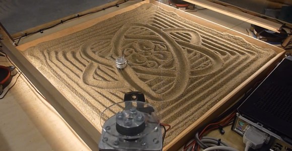
[David] has created a four cable drawing machine for the Telus Spark Science Centre in Canada. Hackaday has featured [David’s] unconventional drawing contraptions before, specifically his center pivot pen plotter. The drawing machine is a new take on a drawbot, and could be considered to be close cousins with [Dan’s] SkyCam. The premise is simple: A stepper motor with a reel of string is placed at each corner of a square. The strings for all four motors come together at a center weight. When all four strings are taut, the weight is lifted off the drawing surface. When a bit of slack is added into the strings, gravity pulls the weight down to touch the sand.
It’s at this point that a simple premise becomes a complex implementation. Moving the weight in one direction is a matter of reeling out string on one motor, and reeling in string on the other. But what about the two “un driven” strings? They have to be slack enough to allow movement in the driven direction, but not so slack that the weight can dig in and tumble on the sand, causing a tangle. To handle some of these questions, [David] called on [Kevin] to write some software. [Kevin] created a custom kinematics module for LinuxCNC to control the drawing machine. The drawing machine runs on Gerber Code, similar to a CNC. Simply feed the machine Cartesian coordinates, and [Kevin’s] module converts to steps.
The hardest part of the building the machine was creating a homing system. Be it a CNC, 3D printer, or a four cable drawing machine, any stepper motor based system has to have a home position. Stepper motors are open loop systems. They are very precise to move, but there is no way to tell where they are at any given moment in time. The most often used method is to get to a known “home” position and use software to keep track of steps. [David’s] problem was getting to the home position in the first place. If he doesn’t know where the weight is, he can’t reel out too much string or he’ll wind up with a tangled mess. His solution was actually pretty simple. He commands one motor to reel in and tells the others not to move. The moving motor is stronger than the holding torque of the other motors, which allows it to pull the weight up until it hits a switch on the pulling motor’s mount. This type of “tug of war” makes all sorts of noise, and requires a stoutly built machine. The results speak for themselves though – [David’s] machine looks great!


please enable fullscreen in youtube !!!!
Or even better, use a completely different video streaming service instead.
Fullscreen works for me.
Looks like the four wires are attached to the corners of the weight. It might be somewhat more accurate if they were all connected to one point on the top, so that the weight always remains vertical.
I just noticed this but thought that the weight could then wobble on it’s top center mounting and you’d lose a lot of precision.
Doing it the way it is being done here you could finesse some additional movement into the weight to add little “twiddly” movements to it while its x-y coordinates are being held steady.
Great post and great comments all making me think a little on a snowy Sunday which isn’t a bad thing.
Very Creative!
Love it – however, why four cables and not three? Three is enough to define position in all three axes. I admit, it wouldn’t fit so nicely around a square table, but you wouldn’t have to calculate an “extra” motor setting which is really redundant.
Reminds me of the ball bearing + sand artworks this guy does:
http://www.taomc.com/art_machines/sisyphus.htm
Yeah, 3 would be enough. Seems like an interesting project. Though I’d like to build a machine that can pick and place blocks or better yet something much heavier
I made a three-wire one for picking stuff up as a demonstration. The accuracy wasn’t that great, due to wobbliness and poor accuracy in homing:
http://essentialscrap.com/deltarobot/
Three wires makes the work area quite small unless you make the robot very large. I think four wires is better, and probably less wobbly also.
This 4-wire robot is great. I have a 3-wire one that used Jpa’s for inspiration that’s sized to do large minecraft blocks: http://def-proc.co.uk/b/zdtbn
You can improve the alignment by using 2 wires on each corner to give parallel linkages like on a standard delta, but I was surprised to find that the kinematics for the 4-motor robot is not much worse than the 3-motor. I was going to go for ultrasonic pings for echolocation of the head to determine initial position.
Three wouldn’t allow you to escape the triangle formed by the motors.
It is kinda hypnotic to watch that moving around. interesting way to implement a 4 axis movement system.
This would make for an interesting Tic-Tac-Toe display. Play against the computer or another visitor.
Buhl Planetarium in Pittsburgh used to have a relay-based TTT machine, and it was always in use.
Whoever edited or submitted this should probably learn that the ‘gerber’ format for pcb manufacture and gcode are not the same. As per the summary, this machine runs on a custoom plugin for linuxCNC that implements the kinematics for this setup. On the input side it still takes normal gcode (.nc or .gnc files).
Gcode is the common language for CNC machines.
So that’s how crop circles are made!
Yes the secrete is reveled 4 UFOs come down and fight for control over a wrecking ball with winch cables. lolz
At our university there is actually a magnetic version of this, with a metal ball plowing through the sand, it looks really cool. What it can’t do is lift the ball like this machine can.
http://scienceblogs.com/catdynamics/2009/04/27/kitp-zen-of-kinetic-art/
This is what I wanted to do to add CNC to an old pattern torch. They have a horizontal arm with two free joints, like a SCARA robot but without motors. What moves it is an adjustable speed gear motor with a knurled, magnetic shaft directly above the torch (gas or plasma).
A steel pattern is held above the arm for the magnetic shaft to roll around. The pattern has to be 1/2 the shaft diameter smaller all around than the part being cut. Sharp outside corners can’t be cut due to the way it rolls around and a too sharp inside corner can get the shaft stuck. Another problem with a too sharp outside corner is the magnet can come unstuck from the pattern which will have the torch drifting across the metal stock. Not a good thing.
To add CNC would be simple. Build a frame to support a stepper motor at each corner. From each motor extend a cable with a ring on the end to slip over the magnetic drive shaft. With the right mathematical function the motors can wind their cables in and out while keeping them all free of slack.
It’s that last bit which was the stumper. Nobody had bothered to do the software yet. It should be simpler than this sand drawer because the pattern torch only moves in a 2D plane so there’s no Z axis to futz with.
I chuckled a bit when I noticed the video is 3:14 long.
It would be neat to stick the contraption underneath and attach a strong magnet then drag the ball around like magics on top.
I liked the part where it drew a maze and then went through it.
Too bad the LinuxCNC kinematics wrapper is not shared.