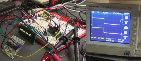
The inductor is an often forgotten passive electrical elements used to design analog circuitry. [Charles’s] latest proof of concept demonstrates how to measure inductance with an oscilloscope, with the hopes of making a PIC based LCR meter.
It is not that often one needs to measure inductance, but inductors are used in switching regulators, motor circuits, wireless designs, analog audio circuitry, and many other types of projects. The principles of measuring inductance can be used to test inductors that you have made yourself, and you can even use this knowledge to measure capacitance.
[Charles] originally saw a great guide on how to measure impedance by [Alan], and decided to run with the idea. Why spend over $200 on an LCR meter when you can just build one? That’s the spirit! Be sure to watch [Alan’s] and [Charles’s] videos after the break. What kind of test equipment have you built in order to save money?


Yay, I’m comment No.1 ! :)
Greetings from Ireland!
The use of Youtube Anti-shake algorithm should be outlawed!
Why? I prefer the distortion over the shakiness.
I don’t.
One thing it can’t do is correct for parallax.
@Charles, this is already been done on both pic and atmel. Do a google search for lm311 pic inductance meter. Neil Heckt did the original one using a pic way back in 1986, http://www.aade.com/lcmeter.htm. Then in 2010 I refactored the pic code to run on an atmega8 or atmega168, http://www.dansworkshop.com/2010/04/inductance-meter/
You mentioned the 74HC14 being used as an oscillator. The oscillation frequency is key. In the LM311-based circuits also, all it is doing is oscillating the tank and calibrating against a known capacitor, and then doing that algebra you mentioned. There’s nothing really about catching that “first pulse”. It is strictly a frequency meter that does the math for inductance calculation. Flip a switch and you have a capacitance meter as well.
Here’s the calibration formula that I used on my atmega: (line 176 in lcmeter.c)
// do some floating point:
Cs = square(F2 * 5) * (.00000000092 / (square(F1 * 5) – square(F2 * 5))); // this should fit in a 64-bit value
Ls = 1 / (4 * square(M_PI) * square(F1 * 5) * Cs);
The only constant in there is the “real” value of the 1nf calibration cap. Then on line 192 of lcmeter.c is the running calculation. Download lcmeter.zip from the dansworkshop site and there’s lots in there to give you a jump on the math. There is even some handy stuff in there for auto-ranging.
What kind of oscillator is that with the lm311? what is the function of that comparator?…
I can’t understand that circuit
These inductance meters that oscillate a tank circuit, and then measure the frequency, are making some assumptions about the inductor which need to be understood. An inductor may measure 22uH at 670KHz, but a different value at other frequencies. This is due to parasitic capacitance in the turns of the inductor. As long as the inductor is going to be used somewhere near the measurement frequency, the assumption is good. But the inductance can vary quite a lot over a range of frequencies.
The same is true of capacitors, there can be parasitic inductance that should be accounted for. It’s probably not as much of a concern as the parasitic capacitance I mentioned above for inductors. Not only that, but capacitors usually have their values printed on them, so the use of a LC meter to identify capacitors isn’t as likely. If you’re making tesla coils and measuring homemade caps then you don’t know their capacitance other than measuring it. In that case, yes you need to account for parasitic inductance because the leads from the coil to the cap bank may be long will introduce more inductance into the circuit.
If the inductors are for power electronics you need also to consider core saturation, that will render this LCR meter partially useless
The “LC” meter is also useless for measuring parameters for filter capacitors for building switch mode supplies. The important parameters such as ESR and parasitic inductance cannot be measured in a simple LC tank circuit. The LC tank with significant values of capacitance would have very low resonance frequency resulting in low resolution assuming the oscillator would start in the first place.
ELM-chan’s “Power Inductor Checker” has a good explanation of the theory and measurement technique for finding out the saturation current of an inductor. (Scope required)
The “Digital Dipmeter” on his site is what you would want to use for wireless work.
http://elm-chan.org/he_i_e.html
G4HUP has also produced a nice LC meter kit. Our radio club had great fun building it http://www.sadars.com/lcmeter.html
For a dsPIC based LCR meter look at the 3rd place winner of the 2007 Circuit Cellar PIC contest.