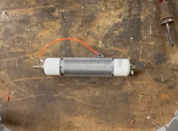
Although it dates back to the early days of the Marconi Company in the 1920s, the Franklin oscillator has remained a relatively obscure circuit, its memory mostly kept alive by ham radio operators who prize its high stability at higher frequencies. At the core of the circuit is an LC tank circuit, a fact which [nobcha] used to build quite a precise LC meter.
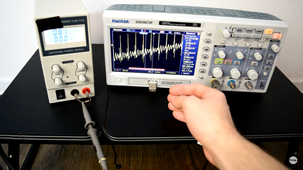
 The meter is built around two parts: the Franklin oscillator, which resonates at a frequency defined by its inductance and capacitance, and an Arduino which counts the frequency of the signal. In operation, the Arduino measures the frequency of the original LC circuit, then measures again after another element (capacitor or inductor) has been added to the circuit. By measuring how much the resonant frequency changes, it’s possible to determine the value of the new element.
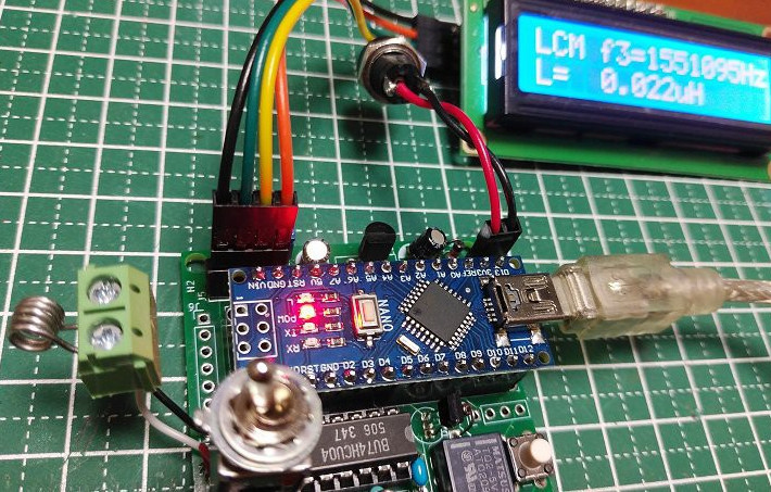
Before operation, the meter must be calibrated with a known reference capacitor to determine the values of the base LC circuit. In one iteration of the design, this was done automatically using a relay, while in a later version a manual switch connects the reference capacitor. Because the meter measures frequency differences and not absolute values, it minimizes parasitic effects. In testing, it was capable of measuring inductances as low as 0.1 µH.
We’ve seen a few homebrew LC meters here, some battery-powered and some rather professional.