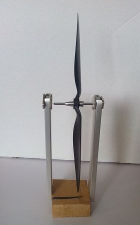
[Danijel0frk’s] friends may call him unbalanced, but his propellers are always spot on. His well-balanced props are thanks to this magnetic balancer he built from scrap PC parts and pilfered office supplies. Propeller balance has always been important for radio controlled models. Flying for hours with a poorly balanced prop can wreak havoc on an air frame and the radio equipment within. With today’s drones and R/C vehicles carrying cameras, accelerometers, and gyros, propeller balance has become even more important. A vibrating propeller can ruin a picture at best. At worst it can throw gyroscope and accelerometer readings off and cause a crash.
[Danijel0frk’s] balancer is based upon several commercial designs. A steel shaft from a CD-ROM drive is cut and the ends ground to points. A propeller to be balanced is mounted to the shaft. Propellers don’t all have the same hole size so two pen tips are pressed into service as self centering mounts. [Danijel0frk’s] picture shows one tip pointing toward the prop hub while the other points away. The balancer will work better if both tips point inward, ensuring the shaft sits directly in the center of the propeller hub’s hole. Hard drive magnets suspend the prop and shaft from a drive rail and wood frame. We should note that this type of balancer will only perform a static balance. Dynamic balance would require the propeller to be spinning on a motor with force sensors on the shaft. To perform a static balance, material is added to or removed from the propeller until it balances in any orientation. Click past the break for a good tutorial video on balancing.
[via Instructables]


This post gave me a great idea for a free-floating propeller based deskfan for the summer months.
Interesting idea but remember that the force it moves air with is going to be pushing back, also simply balancing the blades isn’t enough if the surface areas are dis-similar enough to cause uneven thrust, unless the gyroscopic effects keep that in check. (think of what would happen if a balanced counterweight and a blade were spun, the blade would exert forces parallel to the axle)
Could build a different axle with wounded copper wire in the center with an extra magnet (ie: simple electric motor.) You’d probably have to get creative with the axle in order to prevent from interference of the other magnets…could be hard to make it work properly – I might try it, too!
I made mine from Lego. Works just fine too.
Just wondering … if an unbalanced propeller will introduce noise into an accelerometer and gyro, has anyone done a before-and-after to measure the improvement using an accel/gyro? Is it possible to look at accel/gyro data to detect a bad prop?
One of the guys over at homeshopmachinist used an accelerometer to measure balance. You need absolute shaft position to do any good though and that means an encoder.
I was reminded of the dynamic tire balancer the Ford dealership had in the 1970’s.
It had a “jack” the axle was set on and a couple motorized rollers to spin the tire/wheel (in situ) and a strobe light. (connected by cables) The mechanic would chalk an “X” on the tire near the valve stem (chalk was easier to see while strobing) and spin up the tire. The jack sensed the vibration of the tire/wheel assembly and flashed the strobe. The mechanic noted where the “x” was during strobing (like the tire was the face of a clock). The wheel weight was needed at the 12 o’clock position from where the “X” showed up during the spin.
Yes that’s quite simple on some systems. The Adrucopter guys have written a tutorial on getting a graph of the accelerometer data out of the APM2 controller modules. Despite my my controller board being mounted on a squishy pad (precisely to prevent vibration from affecting the the controller) with unbalanced props I still ended up with +/-5g hitting the controller. To be within spec I needed +/-3g which I easily did after balancing the props.
What was really good was the results of doing a vibration test and then hitting a post on the house while landing. That kind of threw off my readings a bit, not to mention breaking the balanced props under test :-)
Frequencies above the rate of change of the accel’s may still cause much garbage in their output. The speed of the ones I know of are not fast enough to read the vibrations of an out of balance prop, but still would be flooded with junk from it.
I statically balance fan blades on the motor shaft by holding the motor and rotating the whole thing back and forth 20 degrees or so consistently. This cancels out the friction and the blade will drift to the heavy side or show no bias if balanced. You can move it and repeat the test and it never lies. It’s quite sensitive but won’t work with coggy magnet BLDC’s on modern stuff. Wouldn’t question the setup except the use of inkpen parts that are “conical” and how they fit on machined parts.
I like your method, thanks for sharing it! Just curious, where do you trim off the excess weight? Or do you put a drop of superglue on the blade to counteract?
here’s a thread on the topic that I created on rcgroups. Getting a good static balance can go a long way towards getting a balanced moving prop, provided the entire system is fairly precise. http://www.rcgroups.com/forums/showthread.php?t=1747572
Static balancing is snake oil. Only dynamic balancing makes sense.
I look at Static balancing as the first step to balancing. Once that is done, you can test to see if dynamic is needed.
Agreed 100% (and i have quite a bit of real world experience to qualify that)