[Pixel] just sent in this automotive hack which disconnects his car charger when the vehicle stops moving for at least 10 minutes. Why would you need such a thing? The 12V outlet in his vehicle isn’t disconnected when the ignition is turned off. If he leaves a charger plugged in when parking the car, he often returns to a drained battery.
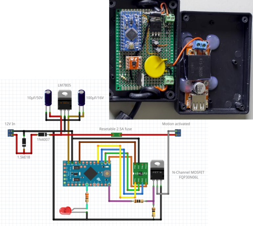
The fritzing diagram tells the story of this hack. He’s using a 7805 to power the Arduino mini. This monitors an ADXL362 accelerometer, starting the countdown when motion is no longer sensed by that chip. At the 10-minute mark the N-channel MOSFET kills the ground side of the outlet. Good for [Pixel] for including a resetable fuse on the hot side. But it was the diode all the way to the left that caught our eye. Turns out this is part of a filtering circuit recommended in a forum post. It’s a Zener that serves as a Transient-Voltage-Suppression diode.
Another comment on that thread brings up the issue we also noticed. The 7805 linear regulator is constantly powered. Do you think putting the uC into sleep and leaving the linear regulator connected is an adequate solution? If not, what would you do differently?


I’m all for a good hack, and I applaud his work, but this seems like over-complicating something really simple. Why not simply use a relay triggered by the ignition line?
If you wanted to make it a little more hack-worthy then perhaps use a voltage divider / transistor combination. This way you can take advantage of the fact that when the car (alternator) is running you’re seeing a larger voltage than when the car is not running. A properly chosen voltage divider around the threshold voltage of the transistor should allow a clever relay triggering mechanism that only activates when the car is running whilst using minimal components.
I’m curious to know what he’s leaving plugged in. My car doesn’t disconnect either, and my cell/tablet chargers don’t do nearly enough to drain my car battery. With a linear regulator to power the circuit I think he’d be spending more power on the monitoring circuit.
1 * PNP transistor, 1 * 12 Volt Zener Diode, 1 * 1K ohm resistor –
12V IN to Emitter
12V OUT to Collector
Base to 1K
1K to zener cathode
zener anode to ground
done!
Yeah zeners work too. I dunno, for some reason I really dislike them :-) Plus the zener would really need to be 13V which are harder to come by.
The advantage of the voltage divider is that you can tweak it to whatever threshold you need based on your battery/alternator setup.
Because then he wouldnt have an excuse to piss away $50 worth of parts in order to somehow use a Arduino, I’m guessing he isnt aware of everything else in his car which slowly drains the battery either.
We must find a way to harvest anger. This person is a likely candidate.
Or he could’ve just relied on the fact that when the engine is running, you have about 13.8-14.4v, and when the engine is off, it’s quite a bit under 13.5v
I believe that is what the commenter is suggesting.
Nope. The commentor was suggesting he use the ignition line. It’s a line that is actually switched on and off by the position of the key. Any car I have ever seen has them. They plug into the radio, that’s why your radio turns off when you park the car. Often they aren’t rated for much amperage. That’s why you would use the ignition wire to trigger a relay. Car radios work similarly, they use the ignition wire to switch on/off but usually have a separate, always-on wire back to the car battery where they actually draw their power.
Oh, sorry. I just re-read it. I guess he did make both suggestions.
+1 this.
Anyone who ever installed a head unit or amplifier in their car would know this. I guess I just thought it was common knowledge, but unless you had the same urge for bone shattering bass that I had as a teenager, you might not. :)
+1
Or use the switched accessory source to control a relay (as has been suggested).
Greatly over-engineered. On the other hand, anything worth doing is worth over-doing…. B)
I’d go for the ignition wire / relay solution.
First, It’s simple.
And it has advantages over the other solutions. Unlike the motion sensor it is on whenever the engine is on so you get accessory power when idling.
Also, does the car’s ignition have an accessory position? If so then using the ignition wire + relay solution you can chose to charge when the engine isn’t even running. You don’t get that with the voltage sensing solution. Just be careful not to use so much power you can’t start the car.
If you don’t have an accessory position in the ignition switch then you can put a toggle switch in series with the relay. Just make sure the up position is closed, down is open. That way if you accidentaly bump it you are likely to bump it into the open position and not wear down the battery. This is my setup in one of my cars.
Another idea to consider while doing all of this, if you want to run anything more power hungry than a cellphone charger.. try running a dedicated heavy wire directly to the battery. (Make sure it has a fuse near the battery!). If you want to run big things like power inverters, transcievers, coolers, etc… most cars use pretty small wires for the acessory sockets. A dedicated wire is also usually recommended for things like ham radios because it cuts down on the interference from the rest of the car’s electrical system.
I have a question I want to install a sensor and trigger where the alarms go and off on a door how would that work,
A whole arduino for this?
Couldn’t you do this with one of those springy motion sensors that bike lights use, wired to provide power to a big capacitor that holds a relay closed? When the car is jostled, the spring would wiggle and complete the circuit, causing the capacitor to recharge in an instant. With a big enough capacitor, or a more efficient solid state switch, the cap would serve as an analog timer. When it runs out of power, the relay/solid state switch would open. Then it would use precisely zero power when it was switched off.
My thoughts exactly, except a cap not supplying the relay directly but via transistor + draining resistor to control discharge rate (smaller & cheaper)
I was gonna say a capacitor and a mercury switch. Not an actual mercury-based one perhaps but a wobble-switch. Then yeah, a transistor and a couple of resistors in there somewhere, driving a relay.
Alternatively, a wobble switch and a 555 in monostable mode.
I’m guessing the q-current of this project isn’t much better than a phone charger left running! plus if you’re not moving in traffic for 10 minutes, your phone stops charging. This function could be very elegantly implemented with a 555 timer triggered from Ignition key removal and a relay latching from IG with some basic components. Added bonus – 0mA q-current. What sort of car runs it’s aux socket directly from the battery anyway???
Every vehicle I’ve owned (all GM, 94 or older) have the cigarette lighter sockets wired to an unswitched source.
Because the sockets were originally designed/intended for cigarette lighters, not chargers.
Some cars have always-on lighter sockets, some have them that are only on when the car radio is powered. My wife’s car has one of each (so she plugs the GPS into the switched one and leaves the other for phone chargers.)
Why would you not just wire in a relay triggered by the accessory circuit (which is 0V when the car is off and is likely running right next to the lighter for the radio). This is sort of a cool project but 100% useless. It’s even detrimental because the IC uses power.
Just use the hot wire off the ignition like everything else does to know when the cars off?
Also every car I can think of ive used a cigarette lighter in the ignition needs to be on….
“Also every car I can think of ive used a cigarette lighter in the ignition needs to be on….”
It varies. I’ve owned cars where they are always on and ones where they are only on when the ignition is on or in acessory position. I’ve even owned cars with multiple sockets, one always on and one switched to the ignition!
My dad had a Ford pickup in the early ’70’s. When you turned on the Emergency Flashers and the radio when the key wasn’t in the ignition, the lights would blink and the radio turned on and off with them!
Switched cigarette lighters used to be an Australian Design Rule for motor vehicles.
This mustn’t apply to ‘power sockets’ as a lot of cars are coming out with them wired to constant power.
Ren, it sounds like there was something screwy with the wiring in your dad’s car.
He seems to be going through a lot of drama for a simple fix. Every car radio has two power inputs, One is always on and the other is ignition off.Seems like the simple answer is to just wire into that. Nothing fancy. If he didn’t feel comfortable with that why not wire into the seat sensor or one of the coolest hacks I can think of would be wiring it to the seat buckle sensor. Then it would serve as a gentle reminder to buckle his seatbelt or he can’t charge anything.
I like that idea!
In one of my past vehicles I wired in a whole radio stack to the ignition, easily accessible through the fuse box.
(not meant to undermine this guys work)
Is it just me or does it seem like a bad idea to disconnect ground and leave the hot side connected when it’s “off”?
Probably ok, it’s not like having 12v floating about will harm anyone. If it was mains, you’d be completely right.
If there are any grounded metal surfaces within reach of the charger lead it could potentially be a problem.
Or if a device was left plugged in, e.g. a tablet with both the charge lead and an audio cable plugged into the radio – the charging circuit would be grounded via the shield of the audio cable and continue to charge.
Also, it bares mentioning that unless the accelerometer is operating in vibration mode this doesn’t help when the car is idling (i.e. if you turn it on in your driveway and are waiting for your wife to put her shoes on). Although I suppose in that case you could just kick the case, which would serve to not only turn it on but also relieve some frustration ;-)
A linear regulator for this is just fine. You don’t even need sleep mode, really. An AVR will draw about 5 mA at 5V / 8 MHz; the linear regulator will draw maybe 15 mA (12 mA plus some slop). A typical car battery is in the neighborhood of 45 amp-hours (45k mAh!), so it’d happily run this controller for about four months at a time!
This is fertile ground for the avr haters, but.. as an learning excersise, this looks like a fun project. Yes there are much easier ways to do this, including things like off the shelf automotive delay relays, but if you want to learn about microcontrollers, AVRs, and low power use, this little project will raise a lot of useful questions. The 7805 will wate power, but not the 1A or so that a USB charger uses.
Simplifications.. forget the USB charger, use one switching regulator module (perhaps one of the ubiquitous LM2596S Adjustable 3A DC-DC buck converters from ebay et al. for both the avr power and the charging output. Use a logic level mosfet to kill the USB charger output or at a pinch, a 5V relay, but that too wasted power, its probably a cheper component though. This will let you learn how the USB charger side of things works.
Suggestions…have a fuse in both the input and output side. The input one to protect the car from the device, the output one to protect the device from whatever is connected to it.
Complications and feature creep… add a display and a couple of buttons to set the delay time, and you have something fun and practical, a charger that will only partially flatten your car bettery, depending on how long a delay you set. Something that can continue to boost your phone/GPS/whatever for X minutes every time you stop the car.
I looked for this comment before posting my own. an accelerometer, an µC, an LDO, and a bunch of analog and digital sensor inputs with a 3.3VDC and 5VDC reference, SPI, serial, and IIC. This is so exploitable. This idea is inefficient for one project, but so very expandable.
“It’s a Zener that serves as a Transient-Voltage-Suppression diode.”
That’s because it IS a Transient-Voltage-Suppression diode. While a TVS is a type of zener, it’s specifically optimized for the purpose of clamping voltage transients, and the large currents that may result. The above quoted statement implies that a normal zener is being used instead.
“The 7805 linear regulator is constantly powered. Do you think putting the uC into sleep and leaving the linear regulator connected is an adequate solution?”
The datasheet for a 7805 quotes the average quiescent current at 5mA. Current for all the other electronics in a parked car varies. I have one that draws 100mA, but 40mA seems to be a more reasonable average. So this is an adequate solution unless the car is infrequently driven, or you plan to add other devices.
It might still be fun to figure out a better solution to reduce current drain, and that doesn’t require access to a switched circuit. Some switching regulators will have lower quiescient current, but don’t assume they all do. And that’s not much fun anyway.
Maybe use a small MOSFET to switch input to the 7805. Detect the voltage rise when the alternator starts running, and switch on the MOSFET. The detector need not trigger at an absolute DC voltage threshold, it could instead operate AC and detect a fast rise (dV/dT) if easier; then the MCU could take over and keep the MOSFET switched on so long as the voltage is high enough to indicate the alternator is still running. Haven’t tried it, and there may be more elegant/established solutions, but that’s the first strategy that comes to mind.
Easier solution: Buy or build a better phone charger with a low quiescent current.
Beating the 5ma of an LM7805 shouldn’t be hard.
It’s not the quiescent current that’s the problem, it’s the current going into charging the phone that he wants to cut off. The charger itself is presumably an unmodified commercial one, connected to the “motion activated” output on the right. Tho if it’s a cheap charger it’s probably just a 7805 anyway. If you’re lucky. A Chinese one might be a resistor, or nothing!
Charging a phone battery from dead to full isnt going to draw an appreciable amount of energy from a car battery. This whole project was a masturbatory exercise in using a Ardurino.
That charger he has is a very decent one as it uses a KIS3R33S module with very high efficiency buck mode with sync rectifier chip that is rated for 3A.
It is silly to use a MOSFET to switch off the charger as the module has an enable pin but unfortunately not broken out to the screw terminal block.
On a lot of cars the fuse fir the cigarette lighter has two posotions, constant or ignition, find iy, move it, or make a patch lead fir the fusebox which does the same :)
My thoughts exactly; routing to the fuse box would be the simplest solution here.
Agreed, add a relay in to keep the loads separate.
Although….
he has everything now to do dead reckoning – combine that with GPS and *that* would be a nice hack :-)
if you own the car (not renting, making loan payments or borrowing) you can wire something into the ignition switch to turn off the port.
another way is if the radio is turned off when the car is turned off you can wire up a slave relay to the power wire that is turned off and then the contacts of the relay to the charge port.
another non destructive way is to use a 12 volt version of a tc54.
since the tc54 limited to 10 volts a resistor network can make it work in a 12 volt circuit so it will turn off when the battery drops below a certain voltage say below 12 volts leaving enough to start the car.
another option is if the car is a manual stick shift you can always push start it if the battery is down.
I agree, but he could also measure the car voltage with a simple microcontroller and detect if the engine is running or not (battery is charging). That would keep him from rewiring the lighter plug, but also will keep it simple.
Why use a simple microcontroller when a simple comparator with voltage divider will do?
Actually you would also need a voltage reference (or use the regulator as one).
Why even try to to use when you can use a power supply supervisor like the TL7702?
It is rated for 20V and you can set the voltage threshold with an external voltage divider and if required you can add hysteresis. In a car, you would want to add transient and reverse polarity protection.
http://tekkieneet.files.wordpress.com/2013/08/undervoltage-cutoff.gif?w=640
This shows a circuit I designed to cut off the load on my DC UPS when the battery voltage drops below threshold. R23/R24 set the threshold and R36 adds hysteresis to the input rising threshold. UB = Battery Supply (after OR’ing diode), VCC= switched output.
I can make modifications even if I dont own the car. Just do it properly so that it cant be noticed (I.E. dont make it a messy hack) I added a second switched lighter jack to a honda and not even the dealer can tell that it was not stock.
Lastly, a tiny USB phone charger can run off of the switched power lead in the ODB-II plug, 30 seconds to add that and is 100% undetectable after the fact.
That zener is gonna take a beating while doing the job it is being used for. Keep spares on hand.
Did you know that the alternator throws out a huge negative voltage spike when you turn the key off? The 1N400x diode is your friend. Set it up to block it rather than short it out because that spike can have lotta amps behind it. Forward biased it’ll pass one amp to your linear regulator, and reverse biased have 0 amps when blocking that big negative spike.
The alternator is commonly set to put out 18v or a bit more to charge the battery when engine is running. With engine off the volts drop to under 15v pretty quick and in just a few minutes drops to 13 or less from just the battery. Turn off your charger whenever less than 15V is seen. No fancy accelerometer needed, just monitor the voltage. .Could use an arduino still, but a $0.79 8 or 14 pin DIP voltage comparator will do it just fine with no code, no fuss, and excellent reliability. One side will monitor the battery voltage and the other side will watch the voltage setpoint using another zener diode.
Check your component specs because automotive includes very low temperatures, and very high. What you built may work great until the temps go way low in winter or way high in summer. Pretty much every data sheet lists the temperature range of guaranteed operation. Automotive is a severe environment.
18V on the car’s 12V bus would be a bit dangerous, I’d think! You’d go through bulbs pretty quickly and stuff would blow. I believe 14.4v is the nominal charging voltage, the highest you should expect to see, falling to 12v or so when the engine’s off.
LFords and other “smart charge” systems get well over 16v. They require special calcium?! Batterys as they boil regular flooded lead acid batterys.
You can expect to see much higher in rare situations. Load dump, battery boiled off, switching spike etc comes come to mind.
http://application-notes.digchip.com/006/6-9084.pdf
“Over Voltage Protection Circuit for Automotive Load Dump”
> The need for over voltage protection is particularly common in automotive 12V and 24V systems where peak “load dump” transients can be as high as 60V.
Not at all. Automotive electrical systems are very hostile environments.
Massive transients can be seen far larger than the usual alternator voltage, and that’s in normal situations, let alone abnormal ones.
This is why you use at least a beefy TVS diode to clamp those transients.
I was addressing Biomed’s point that the alternator is commonly set to give 18v, which would be a constant voltage, not transient. Maybe I’m wrong but it sounds high to me. Of course as you said, there are lots of transients, from all the coils and heavy switching and stuff.
Alternators (generally) should be 14.4V +/- 0.2V IIRC for proper operation. 18V continuous output would definitely fry a lot of components in the car. They are hostile environment, but that’s meant for TVS and surge and noise, not baseline.
Alternators are pretty cool with how they work – they actually use an electromagnet for the rotor with a feedback circuit so that you can easily have a fixed voltage output regardless of the RPM.
A healthy battery should hold 12.6V +/- 0.2V for quite some time after the car has been turned off. If your battery drops to 12V or below shortly after turning the car off I bet you need a new battery.
A friend once had a cabin cruiser boat, just a small one. Used some old engine out of a British car from the 1960s. I imagine because one happened to be around when it was fitted. It’s interesting a lot of the clever hacks they had to do, before components for doing it the proper way were invented. Voltage regulation seemed to be some sort of relay that clicked on and off, perhaps depending on battery voltage.
In a scrap yard, looking for spares for it, we found one of the bimetal car indicator light flashers. Finally I knew what the ticking noise was that I’d heard so much as a kid!
Controlling the rotor’s magnetic field like that is simple and clever. Power stations also use electromagnets in their generators, wonder if they do anything similar? Maybe it would help them keep frequency, regardless of load.
Also found a great book in a pub once, it was one of those neglected books bought by the metre for interior decorating, just there as set-dressing. A good-condition manual for mains electricians, from the 1920s or 30s. Including designing elevator drives, mercury rectifiers, motor-generator sets for radio frequency. Don’t even think vacuum tubes were in it! All sorts of crazy, ingenious stuff! A simpler world had more complex brains, I think! There’s not so many generalists about now, though we can’t afford there to be, experts need so much depth in their field there isn’t room for width.
>There’s not so many generalists about now
More like the bean counters doesn’t want to pay for it. Once you got the basic few years of solid engineering experience, it is quite easy to pick up a few specializations if you have to/transitioned to be wearing a few different hats over time. It gives you a lot more trade-offs/options to solve an issue.
I have worked with a few self proclaimed “experts/specialists” that are too tied up in their *narrowed* fields that do not care/aware of the system level issues their solution causes. The person(s) at the system level didn’t know enough about the problems until it was too late. That was part of my motivation of taking on the extra areas.
I find it amusing that most here are suggesting circuits almost as complicated while only one person mentioned the fuse box.
But hey, while we are having a nerd-out, why not mention the tach sensor (like a real car alarm uses) or even the OBDII port?
Really, if he has used a bare AVR loaded with Arduino and an internal oscillator, he would have used less parts than many of the suggestions here and a small AVR is cheaper than several discrete components too.
To answer the question in the article, no. I don’t think using the sleep mode would make a huge difference because a linear regulator is designed to regulate the voltage by wasting the excess as heat, which it will do even without a load. I wouldn’t be surprised if his battery drains even faster now because the switching regulator in his charger was actually more efficient.
BTW, the arduino mini already has a more efficient LDO regulator built in at the 9V input. The 7805 wasn’t even needed.
> a linear regulator is designed to regulate the voltage by wasting the excess as heat, which it will do even without a load.
You seem to think that it doesn’t make a difference whether there is a load or not: it does. If there is no load, theoretically even a perfect linear regulator wouldn’t waste any energy as heat. The higher the load, the more current, and the more energy wasted as heat (think of a linear regulator as a variable resistor that sits in between the power source and your load). What you’re interested in here is the quiescent current, which is listed in the datasheet of the 7805 as 5mA. This is the current without load.
and the data sheet lies, check it with a amp meter.
Are you stupid? Of course the amount of current depends on load. However, it draws current even with 0A load BECAUSE it drops the voltage by transferring the excess voltage into heat. That’s how a linear regulator works. Just what exactly do you propose it is doing with that 5mA just sitting there? Duh!
And 5mA is a lot. That’s 35mW. I am willing to bet that’s a whole lot more than his charger draws sitting there plugged in his car with no phone attached.
If you put a resistor across a power source, just what exactly do you think it does if it isn’t generating heat?
I swear you people comment on ANY reply with those most pedantic shit just to try to seem smarter than others. You’re not. It makes you sound stupid.
In fact, that *minimum* 5mA across the linear regulator is probably more than the entire rest of the circuit is even drawing. And again, there is already a linear regulator on the Arduino mini. And guess what, even in sleep mode, it will also be drawing some current. So now you have two regulators essentially doing the same thing and drawing current while just sitting there.
So, yes…. it makes very little difference, if any.
35mW is nothing in a car. The wastage gets higher the more current you draw, because 7/12ths of the power is wasted as heat. The more load you draw, the more current passes through the 7805, the more power the 7805 needs to waste.
If you’re drawing 5ma, the 7805 wastes 35mW, yes. If you’re drawing a full amp, the 7805 has to dissipate 7W. That’s the point. The wastage goes up, the more current you draw.
If you were drawing 0 current, the 7805 would draw 0 amps, and would dissipate 0 Watts. In theory at least. In practice the 5mA is just inefficiency in the 7805’s design, it’s not necessary in principle. His point was, the more you draw, the more you waste. Which you “duh”ed at. Duh!
No shit Sherlock.Nobody was even arguing that at all. Did you miss the whole fucking part about the entire circuit likely drawing less than that 5mA anyway? So putting it to sleep helps HOW?
Do you even realize which question I am answering in the article or are you just in a hurry to post some stupid captain obvious comment?
Think about it… if his charger is the worst kind out there, it has a LM7805 in it. And he claims that it is draining his battery. So what did he do? He built a circuit using a 7805 always powered to switch off a 7805 that was always powered.
So, once AGAIN… putting the arduino to sleep will make NO difference because 90% of the current being drawn is in the two regulators in the circuit which are drawing more current than the arduino anyway. And at the very least drawing as much current as his charger was anyway.
Duh!
Some interesting people here: no need to use any swearing, “justice” ;)
> However, it draws current even with 0A load BECAUSE it drops the voltage by transferring the excess voltage into heat.
No: it draws current at 0A output because of inefficiencies. If you check the datasheet, and look at the diagram of the internal operation of the 7805, you’ll see that the “series pass element” would be closed completely, and it wouldn’t “drop the voltage by transferring the excess voltage into heat”. Also, usually you’d have a capacitor on the output, which would keep the voltage at the voltage divider at the same level, keeping the series pass element closed (that capacitor would leak too, but wouldn’t account for that 5mA draw).
Good luck, justice!
James, I apologize for the foul language. I was in a bit of a pissy mood this morning. I understand what you are saying, but we are really talking about two different things. You are wrong in MY context, and I am apparently wrong in yours. What you are stating is hopefully obvious, but honestly… it is unrelated at all to both the question asked in the article or my response.
I appreciate your patience.
In your statement “a linear regulator is designed to regulate the voltage by wasting the excess as heat, which it will do even without a load”, the use of the word “which” has caused the confusion that has lead to this ‘flame war’ lol.
Had you, in some way suggested, that the power dissipation (heat) was roughly proportional to the load current then others would not have misunderstood you.
Also if you read the responses that occurred you will find that they are also (mostly) factual.
If you like ‘flame wars’ then try to use the words: which, that, it, they, them, then, when … as much as possible.
I make mistakes like this often and when I do, I try to clarify myself rather than call people stupid.
No offence intended.
Thanks. I am done arguing. It’s a ridiculous argument in the first place and I should not have engaged in it.
Also surprised nobody mentioned that the voltage will be different between when the port is running off battery vs. alternator. He could have simply monitored that instead of a motion sensor.
How much difference depends on the car.
Lots of people mentioned that, have a look!
I did find a comment mentioning that after I wrote it. My bad.
Interesting build, but overkill. Cars have two 12v lines for car-stereo power. One, for memory keeping is always powered, another is main power and is disconnected when you turn off the engine.
One transistor and few passives and you’re done.
Newer cars dont have a switched live for the stereo, there powered up by activity on the canbus. Makes fitting aftermarket stereos fun. Prob not the case here but worth bearing in mind, gm cars woth this system are getting on 10years old..
i think with a healthy car battery you could fully charge a cellphone 20-50 times. i wonder if this hack really solved his problem
I like the circuit, but I’d have built it more like an LVP motor controller:
http://nuclearpowertraining.tpub.com/h1011v4/css/h1011v4_130.htm
Every laptop built the last few decades has something called powermanagement. If the battery drains below a certain value, the device shuts down. Why can’t a car that costs many time more then a laptop have a device that does something similar: if the battery goes below a certain level the only electrical device that will still get power is the starter.
On my car, If I leave the headlights on they automaticly turn off after about 3 hours.
After coming back to a completely flat battery in my car twice, I stuck a couple of relays triggered off the switched power in line with my headlight switch.
Now it is impossible to leave the headlights on. :) As soon as I shut the engine off, the headlights go off.
As an added benefit, I never touch the switch anymore. But in the event of an electrical issue (Need to drive home on a bad alternator.), I can shut them off.
wow, all the transistors and passives. and microcontrollers. and wow.
I would either switch to keyswitched power at the fuseblock or just put a relay in line with the power port wired up to only be closed with the ignition on. dead simple, foolproof(mostly), and FAR less costly. Not every problem must be solved with the most modern or most complicated part. K.I.S.S.
As others have suggested, detecting voltage is a likely (and more power-saving) solution. One potential pitfall is that depending on the car and where the 12V source is being taken from, it could be regulated 12V.
The simplest solution is to take advantage of the fact that there WILL be a key-controlled 12V source somewhere. I’d personally just poke about in the fuses with a multimeter until I found something that went on and off with the key. Don’t even need to solder anything in that way, just slide a wire into the fuse clip.
There are much better linear regulator chips for automotive application. e.g. Micrel’s MIC29XXX series LDO. It based on PNP pass transistor, so its ground current goes up as its load increases. At very low load (say 10mA), that current is around 0.9mA.
I can’t stress enough about automotive transient protection (as in spikes etc), reverse polarity protection (e.g. someone connected the jumper cable backwards), load-dump (e.g. batter connector comes off and your alternator puts out high voltage etc). Your regular 7805 or Arduino circuit does not protect against these kind of stuff.
The MIC29XXX has built-in reverse polarity and load dump protection. Absolute Max rating: -20V to +60V. Its output is cut off when input exceeds 28V and.the usual thermal/short circuit protection. You want to add a fuse plus a good transorb/TVS for handling the high voltage spikes.
There are also variations of the chip that have On/Off enable pin. You can probably get away with a simple R/C circuit to make a time delay shut off or a voltage divider for detecting the battery voltage.
Yes, I was going to mention the Micrel part too. So many projects I see use 7805 chips. They are cheeeep but relativly power hungry. The 7805 is a great old work horse, but particularly for a portable battery use, something like the Micrel part is much better.
78XX is good for automotive applications. It tolerates 35V in, gives 1.5A out, Extended temperature range versions are easily obtained. Best of all, it’s simple!
Protecting a 78XX is not at all difficult. A blocking diode handles the negative transients and most positive transients can be swamped out by just a large input cap, plus you can add all sorts more protection. Just google automotive power supply and you’ll find plenty of really slick “hardened” examples.
Quiescent current is not much of a consideration here because the automotive environment has large excesses available. Still arguably reducing consumption is always a good thing.
For my own purposes, on the bench, in the car, or on the motorcycle, the 78XX and 79XX series are what I reach for first. It’s just too simple and I’ve lots of stock. Portable battery powered applications are an entirely different matter, but that is a different story.
Our originating author did just fine. His post drew great help in the forum. Wanna bet we can do better?
>Wanna bet we can do better?
Actually, yes. I was working doing testing/design power supply/protection for a company that make automotive product that pass external certify lab test. We have product on trains, trucks and buses.
google for DC10615 (DaimlerChrysler Electrical System Performance Requirements for Electrical and Electronic Components) if you want to see what a car manufacturer wants to test for.
Some of the testing involves low voltage during cranking and they are at 6V which is outside the operating range of a 7805 because it is not a LDO.
>Best of all, it’s simple!
The MIC29XXX is *plug in compatible* with the 7805 if you choose the 5V 3 pin version. This offers an instant upgrade with the added -20V to 60V protection without modifying the existing design. It is even simpler!!!
You can also get 1.5A/3A/5A/7.5A versions with same automotive protection in mind. Additional options like On/off enable, under voltage detection, adjustable voltage are also available (not all at the same time) in different package options.
I meant to say we can do better at providing help instead of just being critical.
There are even better parts than the Micrel for battery operation with lower ground current. Probably should be LDO with DMOS/MOSFET based series regulation or switch mode stuff. I mention this part because it seems to be specifically designed for Automotive application which the 7805 wasn’t.
I found it strange that *most* of the hack site uses very old parts that must have been designed in the late 70’s or 80’s. e.g. 78XX, LM741 etc. There are much better parts made that are 20-30 years ahead. :P
Some how even with google, people seem not being able to have the knowledge to pick out much better made parts/designs for their particular application on their own and simply copy/paste from 3rd hand sources. This situation is getting worse and worse.
The simplest solution is to pull the fuse and use a jumper with an in line fuse to wire it to a bus that is off with the ignition, I did the opposite (switched a socket to always on) in my Volvo. No need to mess with ignition wiring or anything else on the car, no need to remove trim panels, and it’s completely reversible. You can buy patch cables that are perfectly safe and secure for a few bucks.
I’m surprised that nobody else mentioned the accessory position of the ignition switch.
By not using the ignition line to switch the power on and off you lose the ability to bypass the whole thing using the accessory position. Guarding against wearing down your battery is good but sometimes you might want to have power for a few minutes without running the engine. Car batteries are pretty big and can survive this and still start you car!
If you aren’t familiar with the accessory position, most car’s ignitions have a position that turns on all the accessories that normally come on only when the engine is running. In some cars you get that by turning the key backwards. In others it’s a position between run and off.
Ok. I own a 05 grand prix that the radio acc etc stays on after you turn the key off. The radio and xm stereo (separate module) shut off only when the driver’s door opens. The two available 12v ports (one by shifter one inside center console) are always on regardless. I have a bluetooth setup that I run into the xm radio line out since the vehicle came with no line in. I ran the wires for the line in from xm unit hidden in trunk under carpet into the center console where I have the bluetooth plugged in. Can I just splice into the hot wire off of the xm unit in the trunk and run it along the same path as the line out to the center console replace positive on 12v plug in and leave ground cord alone? p.s. only reason I want it to shut off and turn on with vehicle is because when it powers on it can auto connect to my bluetooth phone. Since it is always on I have to manually connect to it every time.
Why would you tap into the ignition switch or any other part of the wiring harness when you can just double tap a bus in the fuse box?
This is the best solution and one that I use for my ham radios wired directly to batter – it will turn on after the batteries has reached a certain voltage and has a selectable timer to shut off when the voltage drops ( car is shut off ) .
http://www.aprsworld.com/apo3/
I have also in the past used a 12v relay – just connect it to a pin of diagnosis jack under the hood that only gets power when car is on . A timer installed on that would do much of the same as the above though not be voltage smart.
Lol. I wanna repeat what evbody is saying… How many arduinos to turn on a led?
One to monitor the power supply, one to monitor ambient light, one to control the LED, one to check the LED actually turned on (and verify its brightness, one to send an SMS alerting you of the LED status, and one to run a web server so the world can check the LED status too.
So, six?
For a completely car/device independent solution – just remember to unplug the freaking device.
Wow overkill much, just wire a relay in before the socket to the NC terminal and then wire the coil into the ignition on wire (there is one that goes to the hifi)
I believe we are all (most of us?) missing something here (I did as well.) He is apparently running several accessories off that “charger” that are left in the vehicle. I had assumed that by the term “charger” that this was used to charge his phone for example, which would imply that he is claiming that the charger itself was draining the battery with nothing plugged into it (assuming he doesn’t leave his phone just sitting there in his car over the weekend.) It would eventually, but it would take quite a while by itself.
That detail is left out of the article, but it only makes sense that this would be case.
Even still, there are many other more appropriate and simpler ways to do this as noted above, especially with just swapping fuses which wouldn’t even be a problem for a leased vehicle or even rental car.
But let’s assume that for whatever reason that isn’t possible or even that perhaps he wants this to be portable between several cars if he moves all his gear with him. Making it external to the lighter port makes a little more sense then.
Given those assumptions, how would we better solve this problem? Well, we’ve hit on the fact that measuring an accelerometer is really not a great way to go about this. If you were idle for more than 10 minutes (which happens often even in rush hour traffic where I’m from) your junk would shut off on you. So, let’s think about this… we need to keep the solution completely external – no modifications to the vehicle – and our goal is to only allow power when the engine is running (more accurately – when the voltage is supplied by the alternator, not the battery.) My preferred solution would be to use the difference in the voltage between engine off and engine running. But then it wouldn’t be as portable between vehicles. Unless we somehow snagged a min and a max and several samples and then auto-adjusted, perhaps.
So given a more fleshed out problem statement (with assumptions), what are the suggestions?
BTW, for future writers, this is a good example of what happens when the problem statement is not really spelled out completely. It really does matter to explain WHY you did a hack.
Use a low power uC and a voltage divider circuit to get the input voltage down to uC range (and proper filtering of course). Have the uC auto-detect the different voltage ranges to determine when the car is on/off. Have a pot to set a variable delay for power-off after the car turns off, and a push button to force the power on based on the same delay. Have an LED that is on when power is flowing, flashes briefly during the last 60 seconds of the power-off delay (so that you can easily push the button to keep the juice on). With a button you can also do “gesture” based inputs. For example a single push toggles power, when turning on keeps it on for the normal delay, if already on then turns off. Triple push keeps it on for 1hr. Quad push keeps it on until you push it again to turn it off. Six pushes followed by a 2-3 second delay followed by three pushes will flash the LED in morse code spelling out “HACK A DAY”.
Oh, you can also have the uC monitor the battery voltage and auto-kill the circuit if it falls below a certain threshold. I’d definitely use a switching regulator as you can get premade circuits for very cheap on eBay. I have a collection of them already in my parts bucket for just such projects.
That actually might be the best solution, only cut the power when it looks like the battery’s getting low. Then you can charge all you like, if the power’s available. Would need tweaking, and perhaps you’d need to measure your battery voltage when nearly empty. That’d be difficult cos it’d mean disabling the charge circuit while keeping the rest of the car electricals alive. Or a hell of a discharger.
Yes, but let’s be clear – there’s absolutely nothing wrong with doing that.
Overkill? Sure, but he learns a lot and gets to play with a uC.
I love a good hack, but for a better design, take a look at what these guys offer. It monitors battery level, and if it drops past a certain point, it disconnects almost everything at the battery — monitoring the brake light line. If you get in the car, step on the brake and go to turn the key, the battery is reconnected and you’re off and running. It’s an ideal workaround for all the small things that drain a battery over time if you tend to leave your car in long term parking at the airport or whatnot.
http://www.prioritystart.com/
Also — many (perhaps most) cars give you way to change, at the fuse block, the behavior of the charging port from always on to ignition dependent. Many just move a fuse from one position to another.
Prime example of over-engineering! I better trick would be figuring out how to re direct the power to the socket only when the ignition is on….this can be done with ONE WIRE! This guy deserves a Heath Robinson Prize.
Just wire in to the power antenna wire or the remote wire on the back of the radio. It is traditionally the blue write. Some bash the over complicated nature or wastefulness of using a uC. Sometimes it’s too see if you can make something do what you want it to do with what is laying on your work bench.
Geez! Another over-engineered hack. My car didn’t have an unswitched outlet, so I installed three of them in the subwoofer box I planted under the dash. Sometimes I leave three devices plugged in and have never been met with a discharged battery. If I had a high-current device, I would just plug it into the original (switched) outlet. All American cars used to have unswitched cigarette lighter jacks. I miss that, but according to what I’ve heard here, they’re coming back….?