If you’ve ever lost gear to lightning or power spikes, you know what a pain they are. Out in rural Arkansas, where [vinthewrench] lives, the grid is more chaos than comfort – especially when storms hit. So, he dug into the problem after watching a cheap AC-DC module quite literally melt down. The full story, as always, begins with the power company’s helpful reclosers: lightning-induced surges, and grid switching transients. The result though: toasted boards, shorted transformers, and one very dead Raspberry Pi. [vinthewrench] wrote it all up – with decent warnings ahead. Take heed and don’t venture into things that could put your life in danger.
Back to the story. Standard surge suppressors? Forget it. Metal-oxide varistor (MOV)-based strips are fine for office laptops, but rural storms laugh at their 600 J limits. While effective and commonly used, MOVs are “self-sacrificing” and degrade over time with each surge event.
[vinthewrench] wanted something sturdier. Enter ZeusFilter 1.0 – a line-voltage filter stitched together from real parts: a slow-blow fuse, inrush-limiting thermistor, three-electrode gas discharge tube for lightning-class hits, beefy MOVs for mid-sized spikes, common-mode choke to kill EMI chatter, and safety caps to bleed off what’s left. Grounding done right, of course. The whole thing lives on a single-layer PCB, destined to sit upstream of a hardened PSU.
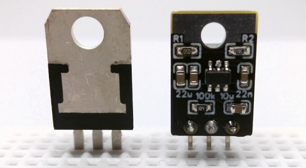
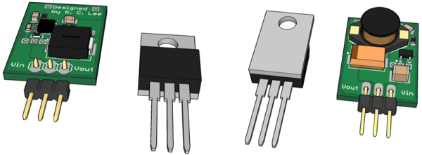
As one of his readers pointed out, though, spikes don’t always stop at the input. Sudden cut-offs on the primary can still throw nasty pulses into the secondary, especially with bargain-bin transformers and ‘mystery’ regulators. The reader reminded that counterfeit 7805s are infamous for failing short, dumping raw input into a supposedly safe 5 V rail. [vinthewrench] acknowledged this too, recalling how collapsing fields don’t just vanish politely – Lenz makes sure they kick back hard. And yes, when cheap silicon fails, it fails ugly: straight smoke-release mode.
In conclusion, we’re not particularly asking you to try this at home if you lack the proper knowledge. But if you have a high-voltage addiction, this home research is a good start to expand your knowledge of what is, in theory, possible.