If you have been wondering what it takes to build a CNC Plasma Cutter then get ready to look no further. [Desert Fabworks] has documented the trials and tribulations of their CNC Plasma Cutter build. Saying it is extremely detailed would be an understatement. They cover everything from choosing components to machine setup.
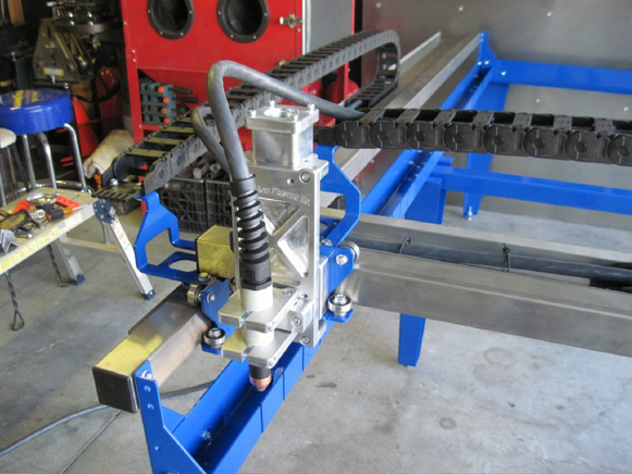
The group already had a CNC Plasma Cutter that they have outgrown. To justify the new purchase the replacement machine would have to have a few non-negotiable features: 4×8 ft cutting area, torch height control, water table, cutting up to 1/2″ steel and be easy to operate and maintain. For the frame and gantry, they settled on a Precision Plasma kit as they felt it was the best value that met their requirements. The electronics package was separate from the frame kit and was provided by CandCNC. Among other things, this package included the power supply, stepper motors, stepper drivers and the torch height controller. For the plasma cutter itself [Desert Fabworks] chose a Hypertherm Powermax65 which can cut up to an inch thick of mild steel and has swappable torches so the main unit can be used for both the CNC table and hand cuts.
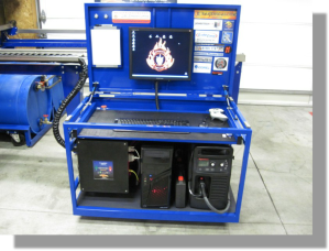
One of the more interesting (and maybe overlooked) parts of the build process was the custom cart that holds the controls, computer, monitor and plasma cutter. The lid of the cart flips up and exposes the computer monitor mounted to the underside of the lid. The keyboard and mouse reside on a pull-out tray. And to make the cart match the machine, it was powder coated blue.
The assembly wasn’t all rainbows and sunshine. A few weeks into using the machine they noticed the X and Y axes were out of square. After replacing a suspect component didn’t fix the problem they decide to physically align the gantry. They started by strapping a pen to the torch mount and drawing right angles on a piece of paper. These lines were then compared to a square. When the direction of misalignment was identified the bolts holding the gantry together were loosened, the gantry adjusted by hand, then the bolts were re-tightened. The same drawing test determined if the adjustment was acceptable or not. As you would expect, it took several tries to get the gantry lined up using this method.
[Thanks Brian]


“then get ready to look no further”
Whew. Ok, I am ready now.
I am looking no further, but I’m not seeing anything!
That cart is inspiring. It has everything. ….I must build one.
Air flow is not adecuated for plasma. Cart is fine.
Not sure what you mean about the air flow?
what’s with the “Excruciating Detail”?
saying it like that surely has negative connotations?
I know that HAD is used to sharing half written up stuff with only a poorly shot video half arsed explanations of stuff etc, but sometimes it’s great to read a really well documented build! and know why people chose various components.
Thanks Frank enStuff and Dan for the positive comments. Getting the CNC table to where it is today was a lot of work, but documenting the entire process was just as much if not more work.
Great job on the tutorial with all that detail I have no fears of building one myself ????!! It’s a lot easier than I thought all it takes is to buy one and bolt it together ???? why didn’t I think of that? ????
This is only useful for people in the USA. Precision Plasma sadly do not sell to anyone outside of the USA.
While precision plasma may only sell in the US all of the other components of the build and the general information applies and works anywhere in the world. I have customers that I have helped and worked with all over the world. Most of my out of country followers are in Mexico, Australia, and scattered across Europe. I have had several customers through other people purchase from precision plasma and have is shipped over seas.
Their cheapest gantry is $3000 :/
The gantry is the main portion of the table and building your own this way is a lot more affordable than going with some of the turn key options out there. I have seen and used a lot of tables. I use the heck out of the table from Precision Plasma and could not be happier. So sometimes quality and reliability is worth the price.
Can I get the Bill of Materials, you used to create the plasma cutting CNC?
I’m sorry I do not have a prepared list but if you follow the build website at http://www.cncplasmabuild.com you will see just about everything I used
Thank you so much ! Couldn’t be more grateful.
I have one more question, in most of the plasma tables I found the grates to be teeth-like, why is that?
Moreover, why do industrial grade CNC machines don’t use PCs but rely on FANUC, Simens etc.??
You will see the teeth type grates so there are less contact points to the metal being cut. Because when the plasma is cutting a piece and it crosses a grate you can get marks on the back side but rarely is this a problem. Mine are flat no points and it has never been an issue. Most of the time I see the teeth grates on laser machines. As far as the reason for the lack of pc’s in industrial machines I’m not sure on that.
Hi, what dimensions did you use for the cable chain?
3.5 in wide by 1.5 in tall. Next time I would go a little bigger always seems down the road you want to add more things.