Handheld Game System Powered By Arduino

DIY Handheld Game System

These days, it’s easy enough to play games on the go. If you have a smart phone, you are pretty much set. That doesn’t mean you can’t still have fun designing and building your own portable gaming system, though.

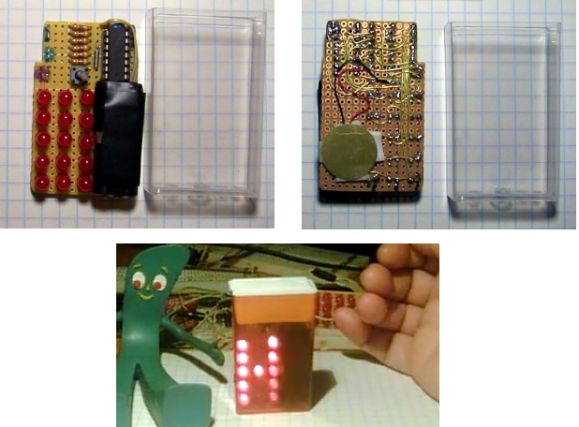
[randrews] did just that. He started out by purchasing a small memory LCD display from Adafruit. The screen he chose is low power as far as screens go, so it would be a good fit for this project. After testing the screen with a quick demo program, it was time to start designing the circuit board.

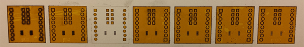
[randrews] used Eagle to design the circuit. He hand routed all of the traces to avoid any weird issues that the auto router can sometimes cause. He made an efficient use of the space on the board by mounting the screen over top of the ATMega chip and the other supporting components. The screen is designed to plug in and out of the socket, this way it can be removed to get to the chip. [randrews] needs to be able to reach the chip in order to reprogram it for different games.

Once the board design was finished, [randrews] used his Shapeoko CNC mill to cut it out of a copper clad board. He warns that you need to be careful doing this, since breathing fiberglass dust is detrimental to living a long and healthy life. Once the board was milled out, [randrews] used a small Dremel drill press to drill all of the holes.

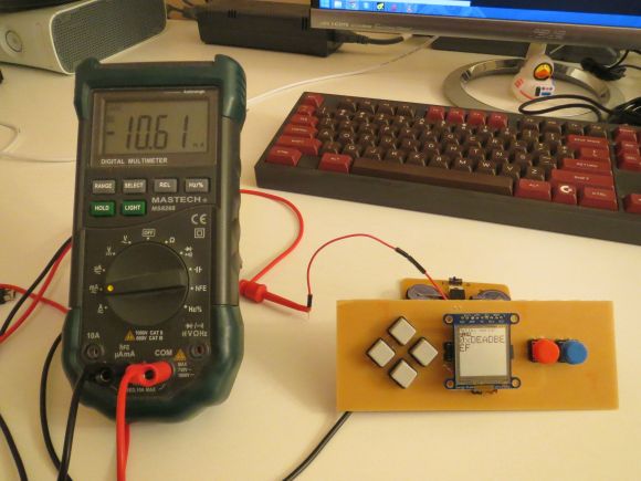
The final piece of the puzzle was to figure out the power situation. [randrews] designed a second smaller PCB for this. The power board holds two 3V coin cell batteries. The Arduino expects 5V, so [randrews] had to use a voltage regulator. This power board also contains the power switch for the whole system.

The power board was milled and populated. Then it was time to do some measurements. [randrews] measured the current draw and calculates that he should be able to get around 15 hours of play time using the two 3V coin cell batteries. Not bad considering the size.

[via Reddit]

An Introduction To The BeagleBone PRU

BBB 
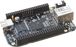
While the BeagleBone is usually compared to the Raspberry Pi, there are a few features that make the ‘Bone a vastly more capable single board computer. There is a small difference in the capabilities of the processor, but the real power of the BeagleBone comes from the PRUs available: two small cores that give the BeagleBone the hardware equivalent of bitbanging pins. [Texane] has put up two great tutorials for using the PRU in the BeagleBone that should be required reading for every BeagleBone owner.

The first tutorial goes over the capabilities of the PRUs in the BeagleBone and setting up the software environment to develop your own hardware interfaces with the PRU. While writing code for the PRU has usually involved the Beagleboard packages, TI has recently released a version of Code Composer Studio that gives the option to compile C code for the PRU.

[Texane] used this C compiler to rehash the earlier, assembly only PRU program, making development significantly easier. There’s still a bit of inline assembly, and the inline assembly support isn’t as advanced as in GCC, but it’s still much easier than the assembly only variant.

While [Texane] is using the PRU in his BeagleBone to develop something at a synchrotron facility, three are a few things where really fast hardware bitbanging comes in handy: it can be used to make a video card for a vintage mac, or any sort of VGA video card, really. Very cool stuff, especially now that you can write something in C.

Hackaday Links: June 22, 2014

hackaday-links-chain

Solar Freakin’ Roadways! There’s been a lot of talk about how solar freakin’ roadways are an ill-conceived idea, and now [Dave Jones] is weighing in on the subject. Highlights include a quarter of the solar power generated being used to light the LEDs that form the lane markers, something that could easily be accomplished with paint. Oh, the solar freakin’ roadway campaign is over. Just over $2.2 million, if you’re wondering.

The Game Boy Micro is the best way to play GBA games, but finding one for a reasonable price just isn’t going to happen. [John Sparks] is making his own Macro Micros by casemodding a DS Lite.On the subject of Game Boy mods, [koji-Kendo] is improving the common frontlight Game Boy Color mod with optically clear UV curing glue. Without glue on the left, with glue on the right.

Need to label a panel with the function of all your switches and dials? Yeah, you could drop the panel into an engraver, till the engraved letters with enamel, or do some electroetching. You can also buy a pack or rub-on letters, available in any Michaels, Hobby Lobby, or the like.

MSI Afterburner is a utility that allows you to play with settings and monitor performance on MSI graphics cards. [Stephen] made a little device for MSI Afterburner that displays the current FPS and GPU load on an external LCD. Handy, seeing as how FPS and GPU load is the one thing you’ll want to know when you’re gaming fullscreen.

Realtime cloudmaps of the Earth. Using reasonably recent images take from five geostationary satellites, you can stitch together a real-time cloud map of the entire Earth. Here’s the software to do it. Now all you need is a projector and pair of frosted acrylic hemispheres, and you have a real-time globe.

Say you have a Kickstarter in the works, and you’re trying to figure out all the ways to get some buzz from the Internet public.. Here’s how you get it to the front page of hackaday.io using a bit of Perl. “So far, this page has been updated 02578 times.”

One-Off Kapton Solder Masks

soldermask

With the proliferation of desktop routers, and a number of easy methods to create PCBs at home, there’s no reason anyone should ever have to buy a pre-made breakout board ever again. The traditional techniques only give you a copper layer, however, and if you want a somewhat more durable PCB, you’ll have figure out some way to create a solder mask on your homebrew PCBs. [Chris] figured Kapton tape would make a reasonable soldermask, and documented the process of creating one with a laser cutter over on the Projects site.

The solder mask itself is cut from a piece of Kapton tape, something that should be found in any reasonably well-stocked tinkerer’s toolbox. The software for [Chris]’ laser cutter, a Universal Laser Systems model, already has a setting for mylar film that came in handy for the Kapton tape,

Of course, getting the correct shapes and dimensions for the laser to cut required a bit of fooling around in Eagle and Corel Draw. The area the laser should cut was taken from the tCream and tStop layers in Eagle with a 1 mil pullback from the edges of the pads. This was exported to an .EPS file, opened in Corel Draw, and turned into a line art drawing for the laser cutter.

The result is a fast and easy solder mask that should be very durable. While it’s probably not as durable as the UV curing paints used in real PCBs, Kapton will be more than sufficient for a few prototypes before spinning a real board.

Tic Tac Clock

tic-tac-clock

Here’s an excuse to eat a bunch of Tic Tac candies: once the container is empty it makes a nice little enclosure for your next project. This particular offering introduces a point-to-point clock project that’s a ton of fun.

[Danny Chouinard] did a lot with very little. You can get the gist of the circuit just by looking at the photos above. it uses a 3×5 Charlieplexed LED display (this is given away by the fact that there’s only a few resistors on the board. A bit difficult to see, but between the resistors and the ATtiny84 there is a clock crystal, and on the back is a little piezo buzzer. The one thing that isn’t completely obvious is the power source. Two AAAA batteries, salvaged from a 9V battery, are able to keep the unit running at an estimated 2 years of moderate use.

The video after the break is worth a look though. It shows the various characters and information that can be flashed on the LED matrix. At first it’s hard to tell that the single user input button is being pressed by [Danny’s] thumb.

If you don’t want to build a clock, there are still plenty of reasons to eat a whole container of these mints. You could replace them with a PIC programmer or a discreet camera.

Continue reading “Tic Tac Clock”

Wooden Band Saw Fears Its Wood-Cutting Brethren

DIY Wooden Bandsaw

What is cooler than building a band saw out of wood? Building two, of course! And that is exactly what [Pekka] did. The first was a small bench top model while the second was a much larger version with the saw blade strung between big 13-3/4 inch wheels. For those who are unfamiliar with band saws, they are tools that have a long thin blade that is routed around rotating wheels. The wheels are spread apart to make the blade taut. Unlike the reciprocating action of a jigsaw, saws-all or scroll saw, the band saw blade continually rotates in one direction. These blades are typically thin making it easy to cut irregular and curved shapes.

The frame of [Pekka’s] larger machine is made from 35mm (~1-3/8″) plywood. This proved to be a sturdy frame material. The previously mentioned wheels were made by gluing pieces of oak together, mounting the assembly on a wood lathe and turning the outer diameter down to size. By using multiple piece of wood to construct the wheels allows the grain direction of each portion to be parallel with the blade. This method of construction ensures any expansion/contraction of the wood is uniform around the wheel. A strip of rubber around the blade’s outer diameter provides the friction required to prevent the blade from slipping.

[Pekka’s] friend was nice enough to turn the flanged axle shafts on his metal lathe. These shafts support the wooded wheels and are mounted in pillow block bearings. The upper pillow blocks are mounted to a sliding support that allows adjusting the tension of the saw blade. [Pekka] was not going to be satisfied with a one-speed band saw so he grabbed a motor he had kicking around that originally came from a wood lathe and already had 4 different sized pulleys mounted on the shaft.

This is a great project that shows what can be done with a little desire and ingenuity.

CNC Plasma Cutter Build Presented In Excruciating Detail

If you have been wondering what it takes to build a CNC Plasma Cutter then get ready to look no further. [Desert Fabworks] has documented the trials and tribulations of their CNC Plasma Cutter build. Saying it is extremely detailed would be an understatement. They cover everything from choosing components to machine setup.

The group already had a CNC Plasma Cutter that they have outgrown. To justify the new purchase the replacement machine would have to have a few non-negotiable features: 4×8 ft cutting area, torch height control, water table, cutting up to 1/2″ steel and be easy to operate and maintain. For the frame and gantry, they settled on a Precision Plasma kit as they felt it was the best value that met their requirements. The electronics package was separate from the frame kit and was provided by CandCNC. Among other things, this package included the power supply, stepper motors, stepper drivers and the torch height controller. For the plasma cutter itself [Desert Fabworks] chose a Hypertherm Powermax65 which can cut up to an inch thick of mild steel and has swappable torches so the main unit can be used for both the CNC table and hand cuts.

Continue reading “CNC Plasma Cutter Build Presented In Excruciating Detail”