There are some types of projects that we see quite often here on Hackaday; 3D Printers, Development Boards and Video Game Hardware to name a few. Once in a while we see an optics-based project but those use pre-made lenses. [Peter] felt it was time to give home lens manufacturing a shot and sent in a tip about his experience.
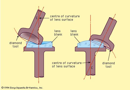
The typical lens manufacturing process starts off by taking a piece of glass and manipulating it into a rough lens shape, either by removing material or heating the glass and forming it in a mold. These lens blanks are then lapped using progressively finer grits of abrasives until the final lens shape and surface finish are achieved. The tool used to lap the lens is very specialized and specific to one lens contour shape. This lapping process can be very time consuming (and therefore expensive) depending on the quality and size of the lens being made.
Instead of using very specific tools to make his lens [Peter] wanted to use standard equipment so it was possible to make different lens sizes and shapes in the future. He did this by writing a parametric g-code file that can be used for any basic lens. The desired lens parameters are manually entered as variables in one location of the g-code file after which the machine control software, LinuxCNC, takes the g-code and drives a 3-axis CNC Machine to mill out a rough shape of a lens.
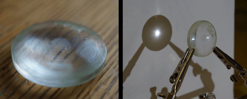
Three millimeter thick acrylic was used in place of glass for this experiment because it is easier to machine than glass. That is not to say there weren’t any problems during the milling process. [Peter] quickly learned that coolant was extremely important in the process. Without it, the acrylic would melt and fill up the flutes of the milling bit resulting in the bit pushing its way through the material rather than cutting through it.
The milling process did not leave a clear finish and required a lot of polishing. After becoming bored of polishing by hand [Peter] tried using a rotor tool… and then burnt a portion of the lens. Lesson learned!
The final lens is not anything special in comparison to commercial lenses but for a first DIY Lens attempt, it is amazing. If you are interested in making your own lenses the g-code file is available at the above link.


With a 6-axis machine and some buffer attachments he could polish it automatically too.
I’m actually thinking of polishing it automatically by making a tool with a curved surface. Not sure if it’ll work, though; also not quite sure how to make it balanced–simply gluing sandpaper would make the surface quite non-uniform.
a circular tool (like a ring) with some give and sandpaper/polishing mit is what i recall seing commercial lenses polished with. may be more forgiving than a curved surface, but will have a much greater polishing time (tho i suppose not an issue is a machine is doing it!)
If you cut your sand paper into flower pedal shapes they can adhere well with good adhesives. When you get above Plus or Minus 8 diopters like building a 16 diopter Bi-Convex, you may have to do a sanding pad change mid polish as they don’t hang on as well. Nice thing about DIY pads vs Coburn and 3M pads is you can make a lens much larger diameter than optical fining and polishing pads will allow, such as spotting scopes/telescopes…
Oculist Nelson ;)
Like this image https://encrypted-tbn0.gstatic.com/images?q=tbn:ANd9GcTG99df1IysvLrrGIxNTvOizUuKGLda2hJZCbZEnh_svdSGnMhN
Oculist Nelson ;)
He really needs to make the decision to go with glass or not before proceeding, obviously the difference in approach and setup is significant.
But if you go with plastics isn’t it easier to just melt the stuff? And with glass for some large lenses they just slowly rotate a container of liquid glass to make a shape, so isn’t the forming plastic by melting it into a shape a much better approach too? Or is that ‘cheating’?
The epoxy he used is not optically matched with the acrylic. Some of the defects in that step (no degassing) could have also resulted in a few of the defects he mentioned in that stage. Epoxy also has piss-poor bond strength on acrylic; CA, solvent bonding, or for a large flat bond like this a two-part acrylate would have been a better choice.
Either way, this is pretty cool. I hate polishing and tedious steps, and given that this was just an acrylic lens and that he had a CNC mill, it might be worth doing it again, except spending that manual polishing time on a mold. The 3020-like mills seem to be only questionably good enough to do metal (though if you were going to sand it and polish down the tooling marks, I guess it’d be good enough anyway), but milling a metal mold and then casting with clear epoxy or preferably some PU would probably get better results with the same amount of work. I’m pretty sure there’s a few examples of this on the Internet, and a few of the resin suppliers certainly enjoy showing cast plastic lenses as an application for their clear resins.
CA = cyanoacrylate? I think I’ll try it again using cyanoacrylate (or just a thicker piece of acrylic, though those are kind of hard to come by), a ballnose single-flute endmill and a properly working Z axis… I just found out that the chinese forgot to lubricate the linear bearings and they destroyed the rails, which I believe is another reason why the finish is so unimpressive.
Try this source for thicker acrylic pieces, I’m not affiliated with them but I’ve run across their name before at work (we use large acrylic sheets):
http://www.tapplastics.com/product/plastics/cut_to_size_plastic/acrylic_sheets_super_thick_clear/510
Given that they apparently block my (russian) IP at the firewall, I somehow doubt they’ll be willing to have business with me :p Nevertheless, this is a very interesting source. Thanks for bringing it up!
Wow, an order on their website has caused my bank to block my card. Happened to me the first time ever!
I’ve had a rather thick block (10 mm or zo) of very clear acrylic from an older LCD monitor.
In recycling this is one of teh parts that fetch decent money; it is clean, claer acrylic.
If you are just experimenting look up your local plastics manufacturer ( of display boxes, sign holders etc. ) and ask them if you can buy a few small chunks. They’ll probably have a variety to choose from and most likely will give you some for free if you aren’t asking for too much.
I gave up polishing to make a lens.. way too much work. I used an existing glass lens to press the heated plastic into the shape I needed.
I was interested in doing a fresnel as well.. but quickly realized why fresnel was and still is in many ways a specialty manufacturing area.
Wait until the winter and experiment with frozen water?
AFAIK Cyanoacrylate is what superglue is made of :)
You dont even need that. A stand, some pitch and some ceramic tile plus the right grit and you can make any lens you want to within a few wavelengths of accuracy. Amateur astronomers have been making lenses themselves for centuries.
Isn’t it possible to flame polish acrylic?
It is, but I wasn’t confident that I could DIY a nice smooth surface. It doesn’t look very repeatable to me, without at least some rotating fixture and a calibrated torch…
Flame polishing does not result in an optical quality finish.
what about some light solvent or vapor polishing?
I’ll wager that making an eccentric lapping tool, such as the one in the above diagram, would probably be worth his time if he plans to do this often. The tool can be fitted to the mill and the process (somewhat) automated.
I’ve often wondered if one could print or mill out a decent pair of mould plates with which to cast a custom plastic fresnel lens from a parametric CAD file, but that would pretty much *require* computer control of a lapping/polishing process, otherwise you could easily destroy a lot of work.
Alternatively, I challenge anyone to hack together one of these beasts for sun-tracking:
http://www.zeitnews.org/applied-sciences/energy/rawlemon-s-spherical-solar-energy-generating-globes-can-even-harvest-energy-
Apparently they are filled with water in order to save material for a large lens volume, which I think would suit them to roto-moulding of something like PET.
The thing is, I don’t really see anything with that product that couldn’t be done using a standard dual-axis tracker and a multi-fresnel lens concentrated PV panel?
What am I missing, besides the aesthetics of it (and possibly – but it seems more hype than anything – the “moonlight” collection along with the diffuse light collection)?
A large sphere of water (might have been better to use mineral oil) used as a lens is nothing new; and in fact, spherical lenses make poor concentrators of light (compared to other lens geometries):
http://www.physicsinsights.org/simple_optics_spherical_lenses-1.html
Again – it seems like the only claim here is marketing hype with the aesthetics claim. It certainly looks more pleasing to the eye than a PV flat panel on a dual-axis tracker (and likely much more pleasing than that same panel with concentrator lenses attached). Whether it is truly more efficient seems unlikely to me, since if it was, PV solar companies would have latched onto the idea decades ago.
It also lacks something that PV panels (even dual-axis tracking ones) can provide: Shade. This can be very important (and desirable) in places with a lot of sunlight and heat (like Spain, where Rawlemon is located).
To anyone interested in a lens making/polishing machine… we have a vintage green lathe??? Fulani Optics Machine With every size disc, glass and different size grits! Don’t know what this is worth. The man use to make telescope lenses. Based in Dripping Springs, Tx
If you could get the cuts clean and set the angle I wonder if fresnel lenses would be possible.
d’Oh, refresh page before posting ;)
I’ve thought about the Frensel lenses. The problem is that you essentially have a singularity at the shear point; in other words, you have a complex horizontal profile that is immediately adjacent to a vertical surface. I don’t think you can machine something like that on a 3-axis mill out of a single piece.
It’s probably possible to use a lathe and a narrow-angle cutter, or make it out of several concentric rings…
This: https://archive.org/details/ProceduresInExperimentalPhysics
The oldschool way of making optics ;-)
If you want to machine glass submerge it in oil and it will dissipate all vibrations outside the glass matrix enabling its normal machining.
A few months ago I made a 400mm diameter planoconvex lens using a similar method. It works reasonably well. For polishing, I first used fine sandpaper to smooth the ridges, and then used a buff mounted on a power drill saturated with a mixture of cerium oxide and mineral oil. I think it’s a viable technique to make rough optics for special purposes, mine was to be used to project the view through a window onto a wall in a darkened room, but it’s not a very practical method to make optics one could otherwise purchase. For my needs, a 400mm diameter lens with a 3500mm focal length was just not the sort of thing you can find available anywhere, so milling it in this method in this case proved to be reasonable.
Now, that is not a lens, but a mind blowing homemade mirror!
Casting a lightweight hexagon back glass telescope mirror
Casting a lightweight hexagon back glass telesope mirror
Don’t know if this helps anyone, but I am a CNC machinist that works now only with plastics, some fairly exotic, like Ultem and PEEK. Maybe this info will help those trying to machine plastic lenses.
The best surface finishes we get in our shop are with odd number multi insert carbide facing tools with zero rake. Best surface finishes I get are usually with a very specific speed, anywhere from 1000 RPM to 1500 RPM, with a finish pass of no less than 0.005″ to no more than 0.010″ stock removal. More specific than that might be trade secrets I’m afraid :) But that should give you a starting point for many plastics.
Speed and feed sync optimization are supercritical for optical finishing on plastics- most will melt some if you don’t get them perfectly matched to your material, it’s obviously more difficult to finish well than metals. Those little details are how we make better parts than the rest.
We do do clear acrylic sometimes, but I don’t work with the stuff, so I can’t advise good feeds and speeds to start with that.
I’m also trained in lapidary work and have used optical lens grinders to custom size pocketwatch crystals, and then hand lap them optically clear. Best results I’ve had lapping glass optical blanks for pocket watch crystals used Alumnium Oxide powder for rapid polishing, and for final polish, use Cerium Oxide- it is by far the best polishing compound for lapping glass. That’s what commercial lens grinders still use, from what I was told. Diamond wheels and constant water coverage are your friend for rough grinding to shape.
Hope some of that helps someone! Thanks AKA the A for the cool pdf link too.
You may consider wearing a respirator, or at least a dust mask.. This should cut down on the clear plastic do do.
It’s the same for lathes, manual or CNC. Tool bit geometry and material and speeds and feeds are all important. If you change one of the three, you should count on having to do some test cuts and experiment with the speed and feeds to find the sweetspot.
We oldtimers scoff at these newfangled carbide insert cutters. Real toolmakers grind their own :-)
A couple of videos on tool bit development, see Oxtool’s channel on youtube.
Tool Bit Development 1
http://www.youtube.com/watch?v=i6-58tjALc0
Tool Bit Development 2
http://www.youtube.com/watch?v=tCrJVYF95aE
Chip Control to Major Tom
http://www.youtube.com/watch?v=yqcVswX4iTc
Now I’m not recommending hogging out chips like he’s doing, heck those chips are bigger than most of the parts I’ve made tooling for, but these methods scale down to small fine detailed work as well. I’ve got to say I respect that man. I’m not sure my skillset scales up to bigger stuff he builds, but I’m not sure his skills scale down to what I did either.
NASA recommends single point diamond turning for optics to minimize polishing time for aluminum mirrors and plain old draftsmans India Ink for the polishing compound, I wanted to try that out myself but haven’t gotten around to it. On the backburner for nearly two decades.
Keep in mind for polishing that the tool side of the polishing has to hold the abrasive, ie be charged with the abrasive, and to hold the abrasive it needs to be softer than the material being polished. That’s why optical pitch is used, or why brass barrel laps are used in steel, and cast iron lapping plates for lapping hardened steel and glass and carbide.
The MILITARY STANDARDIZATION HANDBOOK: OPTICAL DESIGN MIL-HDBK-141 is a useful reference for optics work as well.
It comes down to experience. Many don’t understand how much time that a lot of us machinists have put into running single machines. I explained it once to the Missus like this, if the machines (Wire EDM in my case) were cars driving at 55 MPH, I’ve driven one particular machine to the Moon and back more than twice. Once you’ve logged 2000 hours (one work year) you’ve probably have a pretty good feel for the machine, 20,000 hours and you’re insanely intuitive of it. We rarely did production work, nearly everything was one of a kind, so it was lots and lots of setup. You know you’ve been working when you lose track of how many carbide indicator points you’ve worn flat.
you know if we work somehting like this down to a simple repeatible proses we could make it easy for aid stations to make Negetive grade lenses for glasses (nearsighted) producing anything higher than -3 or -5 right now is kind of hard.
I myself am curintly using over -30 do to extream miopea and cataracks bluring things up
It’s gotten so bad last time i whent to the docs they got the script so wrong i ended up mounting test lenses to my glasses to corect the underpower
Yes i could force the point but the last time they came up with -25 and it took a -2 and -7 lenses to get a decent enough focus my glasses cost nearly 700 a pair without frames as is. i wonder what a – 34 would hit me for
i’d love a rig that would allow me to custom grind pollycarb from eather a blank (genril shape lense but not the final script) or near mold ( basickly the script with just a tad more meterial to grind/polish the finished lense.)
with a combenation of 3d printer to make the premold and a hald desent way to polish and finise the power without going indrustrial would be wonderful
with such high scripts we dont need opticly pure lenses most of the time. we’ll never notise minor defects in relation to our allready poor view of the world :p
This has got me thinking now :p
i need to ffind a sorce for liquid pollycarb (it’s a binery liquid and hardiner for clear )
I can advise you on the old ways of making lenses. I have done glass, plastic and poly carbonate/Lexan from a lens blanks I have poured with resins to the needed front curves. With a protractor for axis/cylinder layout, a cordless drill motor and some “Lap tools” ,that can be 3D printed, you CAN make any ophthalmic prescription you want, including making your own 200 mm telescope main objective lens. Next, get some polishing pads in the rough aprox 120 grit the Med. aprox 400 grit and the polishing felt, as large as you want your lens diameter to be. cut these into flower pedal shapes large enough to polish the diameter of the lens. You need constant water flow to these pedals your cut out and 3M glued on to your Lap tool our just find some online. During the first phase “Roughing” and 2nd phase “Fining” use water but for polishing you need to order online or DIY mix a slurry of rare earth plastic polish that is a bit thinner than pancake bater but not as thin a milk. I would use a separate 5 gallon bucket and pump for the slurry than the bucket and pump used for the roughing and fining water process., Any cross contamination via not rinsing and or not blow drying the lens clean and you can find the grit left overs left some scratches during the polishing phase. Everything needed can be done with 300 watts of solar panels. Get a used trail lens set from China and an eye chart with Red and Green on it lines on it. Grab a few trail lens frames off Ebay. With some advice and some Youtube videos you can be your own Oculist! With practice you can even get exact prescription of a lens using just a wide mouth mm gauge.
Easier is to use a lens clock to read the front and back surface of the lens in diopters the algebraic difference is your lens power. Plus lens is always thicker in the middle minus always thicker on the outer edges of the lens., All of the optics and formulas are kept easy as it is all in metric. Check your front and back curves of the lens with a lens clock or spring for a lensometer uses I found one for $39 used works great!
Would love to pass all of this and more knowledge on to someone that would use it to help others :) I don;t know anyone else that can do this the old way like we use to over 30 years ago :( It is all computerized now which is great unless a large X-class CME pulls an Harrington event on us all :(
I will follow this project and the posts with passion!
Oculist Nelson
A top notch optical manufacture, Gerber, makes a machine that builds a one time use lap tool and on spherical non toric Rx we could get as many as 4 uses out of them. Gerber’s lap tool was a molded foam tool set up & I bet you guys could 3D print a just thick enough example of the rear and or front curves of a lens to hold the tool maker foam to make your on lap tools, that have a embedded shaft kind of attached inner disk that will tolerate the torque needed hold and spin DIY lap tools. It is a science and art to get good at “rocking in” a Prescription. To Rock in a prescription, before cylinder machines, we would do toric (astigmatism corrective lens) in two steps the sphere power and the cylinder where created by rocking the lens back and forth on a given axis to create the correct cylinder curves. Your cylinder back curve needs to blend with the spherical back curve which both oppose the front curve of the lens to create the prescription and with a high torque electric drill motor will spin this DIY tool that is locked into said drill’s key less chuck. I want to team up with a adventurous 3D printer owner to create lens using resins that are visibly clear on the inside and then use a lens pining UV cure coating machine to give the lens it’s last polish phase and optical clarity. We did this all of the time on the polycarb lenses we had to generate the back surface on or the first time someone wiped the lenses they would get scratched so bad it was not usable. I use to UV spin the back side of the lens so they had something clear to wear while we made another lens. A lens that has already been edged down to the frame size is not best as the resin pools around the edges. I hacked the labs motor for more RPMs which helped but not perfect and it creates a thinner less protective scratch coat as well. Best to coat the lens before you edge it down to size, so you can edge off the pooled up area of the UV cured Scratch coat. I use a rechargeable $30 dental UV cure light of ebay (use the orange oval plastic as your lens to view the action taking place inside so you don’t harm your retinas) and a DC motor I can control the rpm’s on. Have this in a box and outside or ventilated as the resin is no joke if you make contact with it. In labs they tun activated carbon filters during use of this spin uv machine it is that bad.
A creative guy could even make progressive lenses if the had all of the progressive lens lens blanks front placed add powers as molds to create a negative to copy the progressive lens front curves and then you can Rock in the back curves. 3D print the back curve then spray UV spin coat it and then connect this new lens to the thin front copy of the lens with a UV activated binder. The problem with this method is the front curve you mate your back lens with needs to be thinner than normal as when you adhere the rear curve to create the prescription it ends up being too thick and heavy for patents to wear on their nose. So you need a front curve with single vision or the type of bifocal you want. Then you need the back curves in a thin lens. but here is the trick, the two lenses should meet with similar base curves so that you have an even amount of the bounding rising to mate the two lens into one lens. If the lenses are mated together with two different curvatures this resin can effect your lenses sphere power, so you would need to counter any sphere change with the 3D printed back side lens. A used lensometer will show you the prescription and reveal any aberration in your lens as well.
Oculist Nelson
***Coburn is the top notch manufacture that makes the great optical equipment but Gerber and them merged with technologies
Almost forgot, run a cold chiller ring in your lens coolant flow and your polish flow it helps with all forms of plastic… maybe machining a piece of material fresh out of a dry ice sandwich could show better optical quality? Just a theory since the quality and finish goes down with the lens, as the coolant temps go up. We kept our coolants cold and our polisher was even more so affected due to lack of being cold enough. We kept the chillers too cold to keep your hand in the polish for long…
Oculist Nelson :)