An image of a grey plastic carrying case, approximately the size of an A5 notebook. Inside are darker grey felt lined cubbies with a mirror, piece of glass, a viewfinder, and various small printed parts to assemble a camera lucida.

Camera Lucida – Drawing Better Like It’s 1807

As the debate rages on about the value of AI-generated art, [Chris Borge] printed his own version of another technology that’s been the subject of debate about what constitutes real art. Meet the camera lucida.

Developed in the early part of the nineteenth century by [William Hyde Wollaston], the camera lucida is a seemingly simple device. Using a prism or a mirror and piece of glass, it allows a person to see the world overlaid onto their drawing surface. This moves details like proportions and shading directly to the paper instead of requiring an intermediary step in the artist’s memory. Of course, nothing is a substitute for practice and skill. [Professor Pablo Garcia] relates a story in the video about how [Henry Fox Talbot] was unsatisfied with his drawings made using the device, and how this experience was instrumental in his later photographic experiments.

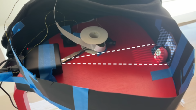
[Borge]’s own contribution to the camera lucida is a portable version that you can print yourself and assemble for about $20. Featuring a snazzy case that holds all the components nice and snug on laser cut felt, he wanted a version that could go in the field and not require a table. The case also acts as a stand for the camera to sit at an appropriate height so he can sketch landscapes in his lap while out and about.

Interested in more drawing-related hacks? How about this sand drawing bot or some Truly Terrible Dimensioned Drawings?

Continue reading “Camera Lucida – Drawing Better Like It’s 1807”

The History Of The World’s First Planetarium

It shouldn’t be a surprise that the idea of a planetarium originated with an electrical engineer, [Oskar von Miller] from the Deutsches Museum in Munich. According to [Allison Marsh] in IEEE Spectrum, he thought about the invention in 1912 as a way to demonstrate astronomical principles to the general public. While it seems obvious today that you can project the night sky onto a dome, it was a novel thought in 1912. So novel that the Carl Zeiss company first told [von Miller] to take a hike. But they eventually reconsidered and built the first planetarium, the Model I.

The engineer for Zeiss was a mechanical engineer by the name of [Walther Bauersfeld]. He was familiar with mechanical devices — orreries — that tracked the motion of the stars and planets. The goal was to translate those movements into a moving projection of light.

Continue reading “The History Of The World’s First Planetarium”

Tiny Prisms Let You See What Lies Beneath A BGA Chip

Compared to through-hole construction, inspecting SMD construction is a whole other game. Things you thought were small before are almost invisible now, and making sure solder got where it’s supposed to go can be a real chore. Add some ball grid array (BGA) chips into the mix, where the solder joints are not visible by design, and inspection is more a leap of faith than objective proof of results.

How it works.

Unless, of course, you put the power of optics to work, as [Petteri Aimonen] does with this clever BGA inspection tool. It relies on a pair of tiny prisms to bounce light under one side of a BGA chip and back up the other. The prisms are made from thin sheets of acrylic; [Petteri] didn’t have any 1-mm acrylic sheet on hand, so he harvested material from a razor blade package. The edge of each piece was ground to a 45-degree angle and polished with successively finer grits until the surfaces were highly reflective. One prism was affixed to a small scrap of PCB with eleven SMD LEDs in a row, forming a light pipe that turns the light through 90 degrees. The light source is held along one edge of a BGA, shining light underneath to the other prism, bouncing light through the forest of solder balls and back toward the observer.

The results aren’t exactly crystal clear, which is understandable given the expedient nature of the materials and construction employed. But it’s certainly more than enough to see any gross problems lying below a BGA, like shorts or insufficiently melted solder. [Petteri] reports that flux can be a problem, too, as excess of the stuff can crystalize between pads under the BGA and obstruct the light. A little extra cleaning should help in such cases.

Haven’t tackled a BGA job yet? You might want to get up to speed on that.

Apple Vision Pro’s Secret To Smooth Visuals? Subtly Substandard Optics

The displays inside the Apple Vision Pro have 3660 × 3200 pixels per eye, but veteran engineer [Karl Guttag]’s analysis of its subtly blurred optics reminds us that “resolution” doesn’t always translate to resolution, and how this is especially true for things like near-eye displays.

The Apple Vision Pro lacks the usual visual artifacts (like the screen door effect) which result from viewing magnified pixelated screens though optics. But [Karl] shows how this effect is in fact hiding in plain sight: Apple seems to have simply made everything just a wee bit blurry thanks to subtly out-of-focus lenses.

The thing is, this approach of intentionally de-focusing actually works very well for consuming visual content like movies or looking at pictures, where detail and pixel-to-pixel contrast is limited anyway.

Clever loophole, or specification shenanigans? You be the judge of that, but this really is evidence of how especially when it comes to things like VR headsets, everything is a trade-off. Improving one thing typically worsens others. In fact, it’s one of the reasons why VR monitor replacements are actually a nontrivial challenge.

An Optical Computer Architecture

We always hear that future computers will use optical technology. But what will that look like for a general-purpose computer? German researchers explain it in a recent scientific paper. Although the DOC-II used optical processing, it did use some conventional electronics. The question is, how can you construct a general computer that uses only optical technology?

The paper outlines “Miller’s criteria” for practical optical logic gates. In particular, any optical scheme must provide outputs suitable for introduction to another gate’s inputs and also support fan out of one output to multiple inputs. It is also desirable that each stage does not propagate signal degradation and isolate its outputs from its inputs. The final two criteria note that practical systems don’t depend on loss for information representation since this isn’t reliable across paths, and, similarly, the gates should require high-precision adjustment to work correctly.

The paper also identifies many misconceptions about new computing devices. For example, they assert that while general-purpose desktop-class CPUs today contain billions of devices, use a minimum of 32-bits of data path, and contain RAM, this isn’t necessarily true for CPUs that use different technology. If that seems hard to believe, they make their case throughout the paper. We can’t remember the last scientific paper we read that literally posed the question, “Will it run Doom?” But this paper does actually propose this as a canonical question.

Continue reading “An Optical Computer Architecture”

This Unique Flip-Flop Uses Chemistry And Lasers

One of the first logic circuits most of us learn about is the humble flip-flop. They’re easy enough to build with just a couple of NOR or NAND gates, and even building one up from discrete components isn’t too much of a chore. But building a flip-flop from chemicals and lasers is another thing entirely.

That’s the path [Markus Bindhammer] took for his photochromic molecular switch. We suspect this is less of an attempt at a practical optical logic component and more of a demonstration project, but either way, it’s pretty cool. Photochromism is the property by which molecules reversibly rearrange themselves and change color upon exposure to light, the most common example being glass that darkens automatically in the sun. This principle can be used to create an optical flip-flop, which [Markus] refers to as an “RS” type but we’re pretty sure he means “SR.”

The electronics for this are pretty simple, with two laser modules and their drivers, a power supply, and an Arduino to run everything. The optics are straightforward as well — a beam splitter that directs the beams from each laser onto the target, which is a glass cuvette filled with a clear epoxy resin mixed with a photochromic chemical. [Markus] chose spiropyran as the pigment, which when bathed in UV light undergoes an intramolecular carbon-oxygen bond breakage that turns it into the dark blue pigment merocyanine. Hitting the spot with a red laser or heating the cuvette causes the C-O bond to reform, fading the blue spot.

The video below shows the intensely blue dot spot developing under UV light and rapidly fading thanks to just the ambient temperature. To make the effect last longer, [Markus] cools the target with a spritz from a CO2 cartridge. We imagine other photochromic chemicals could also be employed here, as could some kind of photometric sensor to read the current state of the flip-flop. Even as it is, though, this is an interesting way to put chemistry and optics to work.

Continue reading “This Unique Flip-Flop Uses Chemistry And Lasers”

Seeing Fireworks In A Different Light

If you’re worried that [Roman Dvořák]’s spectroscopic analysis of fireworks is going to ruin New Year’s Eve or the Fourth of July, relax — the science of this build only adds to the fun.

Not that there’s nothing to worry about with fireworks, of course; there are plenty of nasty chemicals in there, and we can say from first-hand experience that getting hit in the face and chest with shrapnel from a shell is an unpleasant experience. [Roman]’s goal with this experiment is pretty simple: to see if it’s possible to cobble together a spectrograph to identify the elements that light up the sky during a pyrotechnic display. The camera rig was mainly assembled from readily available gear, including a Chronos monochrome high-speed camera and a 500-mm telescopic lens. A 100 line/mm grating was attached between the lens and the camera, a finding scope was attached, and the whole thing went onto a sturdy tripod.

From a perch above Prague on New Year’s Eve, [Roman] collected a ton of images in RAW12 format. The files were converted to TIFFs by a Python script and converted to video by FFmpeg. Frames with good spectra were selected for analysis using a Jupyter Notebook project. Spectra were selected by moving the cursor across the image using slider controls, converting pixel positions into wavelengths.

There are some optical improvements [Roman] would like to make, especially in aiming and focusing the camera; as he says, the dynamic and unpredictable nature of fireworks makes them difficult to photograph. As for identifying elements in the spectra, that’s on the to-do list until he can find a library of spectra to use. Or, there’s always DIY Raman spectroscopy. Continue reading “Seeing Fireworks In A Different Light”