A relative latecomer to The Hackaday Prize, [AltMarcxs] has nevertheless come up with a very interesting tool for fabrication, the likes of which no one has ever seen before. It’s a rotating laser soldering paste applicator, meant to be an add-on to a CNC machine. What does it do? RIght now it looks extremely cool while being an immense time sink for [AltMarcxs], but the potential is there for being much more than that, ranging from a pick and place machine that also dispenses solder paste, to the closest thing you’ll ever get to a carbon fiber printer.
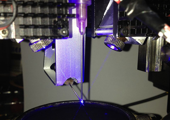
[AltMarcxs]’s build consists of two 3W laser diodes focused just beyond the tip of the syringe. The syringe dispenses solder paste, and rotating the diodes around, [Alt] is able to put a melted solder blob anywhere on a piece of perfboard. He put up a reasonably well focused video demonstrating this.
With a few homebrew pick and place machines making the semifinalist cut for The Hackaday Prize, it’s easy to see the utility of something like this: Putting a board in a machine, pressing a button, and waiting a bit for a completely populated and soldered board is a dream of the electronic hobbyist rivaled only by a cheap and easy way to make PCBs at home. [AltMarxcs]’s machine could be one step on the way to this, but there are a few other ideas he’d like to explore first.
The build also has wire feeders that allow a bit of copper wire to be soldered to the newly formed metal blob. There are plans to replace this with a composite fiber, replace the paste in the syringe with a UV resin, cut the fiber and cure the resin with the laser, and build something much better than other carbon fiber 3D printers we’ve seen before.
 The project featured in this post is a semifinalist in The Hackaday Prize.


I don’t get it; the point of dispensing solder paste on a board is that you can push in components in it, while it’s still a paste, so the components will be flush with the board, and stick in the paste so they don’t move when you (carefully) handle the board. All this won’t work if you melt the solder paste before populating the board, and there are easier ways to tin the pads, if that’s what you wanted to do.
If the whole point was that he can solder thin strands of copper wire to a board, I still don’t get it, because why would you need to do that if you are soldering it to a circuit board to begin with?
Also, shining such powerful lasers on bare metal, which is going to melt and create a round surface with unpredictable reflections seems a bit dangerous; I hope he’s using a safety shield which he just removed to make the video.
See below why,
On laser safety, I use a webcam to look at, the laser are defocussing and main reflection get on the other side (crossed beams), convex blobs aren’t a problem they defocuses even more, BUT concave sinked in solder are.
Don’t worry, I know what I’m doing, I used to repair 1.5KW CO2 laser cutters.
I don’t get it that you don’t get it… Get it?
I had a bit of trouble understanding this one too. Sometimes you just make a cool machine first and find a use for it second. Think of it like a gold wire thermosonic die bonding machine on a larger scale.
http://youtu.be/ssg67GLfTtw?t=13m12s
There aren’t many transparent multi-layer PCBs though.
Aye, I don’t understand the point of it either. PnP machines do not have perfect tolerances. You want all the pads to reflow at once so the parts settle into position. Head in pillow, pad cratering, tombstoning, among other problems are caused by or complicated by non-uniform application of heat across a part.
You also want the parts to pre-soak in heat and eventually warm to the same temp level as the solder to minimize the thermal stress of conductive transfer across the part. Lasers help control the energy input, however you still have to get the whole solder glob boiling and the lead to the same temp for it to stick. You don’t want the rest of the package cold.
See below..
I envisioned a hotplate below (also for the future 3D printing Add-on, b3 high-temp hot end…) but at the moment, let me make small steps.
This is great, maybe not much for solder, but for anything else SLS style, he’s just gotta invent some new pastes that are similar to kittyhair carbon fiber mixes, try some resin’s used in UV curing 3d printers maybe.
It started almost as joke: I have a old broken iPhone (2 pins teared off, very small connector), I told a friend of mine that I gonna repair it, but have to make the machine for this, because I can’t do it manually it’s too small for me.
Anyway I wanted to upgrade my CNC to 3D printing, but the idea of tinkering with Pick&Place, Solder paste got me, I had that 1.8W laser and it melted tin…
Changing the syringe is so easy, so why not use UV-resin print a board where components get glue on, then solder small wires, make another layer with UV-resin add some more components… a 3D circuit board, 3D printed coils… I see endless possibilities.
That why it will be full OpenSource and I hope people use some parts of it (perhaps the laser system is too much for some, then stick a hotplate below and use it to dispense paste + P&P). Why not trying ceramics, conductive ink or graphene ?
Don’t we love to experiment?
Whilst I’m sure this is a cool project to play around with, there’s way too much “it *might* one day be useful for this and this and this…” and absolutely no “it will be able to do this”.
Don’t get me wrong, dreaming and random tinkering had it’s merits. However, amazing multi-function CNC projects where the end goal is unclear are everywhere and they never seem to end up finished. I hope with the HaD prize to spur you on that this is an exception.
where do you get your lasers from?
DTR’s Laser
Also they forget to mention the “Digital” compressor, it’s a really cheap tire compressor 12V where the motor is replaced by a stepper motor.
Less noise, way better pressure+vacuum pulse for dispensing.
My idea materialized, great job picking my brain remotely! Except mine would be roll to roll flexible printed circuits, sort of like a tower of sorts. Substrate layer , layer of photo resist applied, layer for image projection/exposure, strip layer, another 2 for photo resistive solder resist, next stack for solder paste placement, infrared reflow on next layer, finished product coming out the bottom layer, totaling about 8-10 mechanical layers, could fit in the space of a standard rack mount server… looking forward to more results.
Certainly a cool idea. But I think, atm, it’s a solution waiting for a problem. Not a bad situation. There have been a few 3D circuit board printers using ascorbic acid and silver nitrate but the resolution has not been good. Maybe this could be the answer – for substrates that can take the heat of melted tin.
https://www.youtube.com/watch?v=LDpc1-lV5Ns
Wow that is neat. but very slow. I’m trying to think of reasons why you would need to selectively solder. In this case it is because there are no defined pad locations and so if you heated it all up they would slide on the curved surfaces. But in a non artwork realm i don’t see why you would have such a scenario. Maybe liquid/DNA sensors that require exposed contacts.
Hi!
I like this project a lot, and i am wondering something : couldn’t this be used to draw conductive traces on a surface?
if so, it could be a way of printing ciruits. Furthermore, since you can cure resin with it, you could even put a protective layer on top of the circuit afterwards…
Perhaps it could also be used to make some kind of 3D circuits? or even multilayer circuits, with a resin layer between each layer?
Thank you! Was thinking nobody saw this possibility.
A better option than those diodes might be a Coherent FAP module. Fiber coupled and pretty cheap on ebay. Coherent shows them using one on their youtube page to do soldering. I have a bunch of these modules, still need to do something with them someday.
https://www.youtube.com/watch?v=QS8TeascSzA
1000% correct. These modules can be found with outputs of up to 40W at 800 nm. Likely, the absorption will be better than at UV as well. The only issue is that the modules (at least the ones I’ve had experience with) require a large-mode-area fiber to deliver the light to your sample (plus some collimating and focusing optics).
You’re lucky. A diode array is much better although matching the fiber and coatings used with the diode wavelength is non-trivial.
And your definition of cheap and mine vary considerably.
Right now I see no deals on the modules. I do see them go in the $50-$100 range pretty often. As for fibers and optics, coatings are not a big deal. I bought my 800micron fibers off ebay for about $30 each new and a focusing lens with a SMA-905 adapter on it for something like $15. Generic MgF coatings are all you need and are what is found on most fibers and optics.
There are also the Spectra Physics FCBar diode modules. They have the fiber attached to them (DO NOT REMOVE). They use a different fiber connector and the power output is rated differently to the FAPs. In the SP modules the power is the rating of the diode array, the Coherent ones the power is the power delivered at the fiber. You loose a pretty good chunk of power when you couple to a fiber so a 32 watt diode will be putting out powers in the 20’s at the fiber tip.