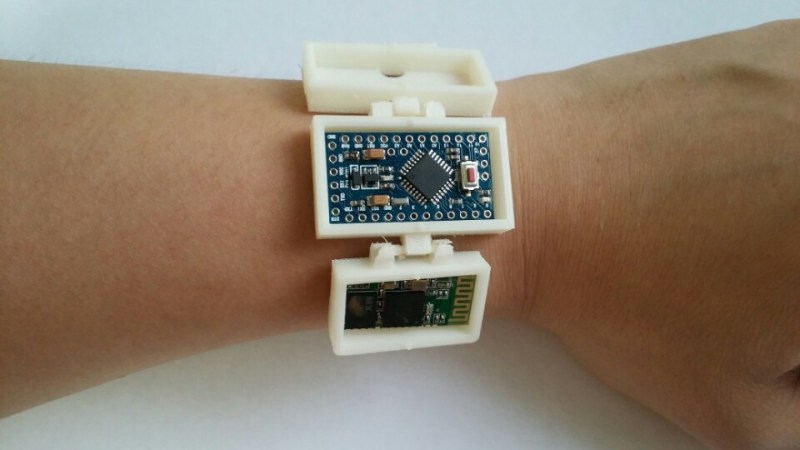
A group of developers have uploaded a tutorial on Instructables showing the steps needed to develop a homemade DIY fitness tracker. The design is the second iteration of an Arduino-based wearable smart watch project of theirs. This time around, they opted to focus more on the monitoring system rather than a visual display. It is called the ‘RetroBand’ and records steps taken and calories burned by the user.
The microcontroller used is an Arduino Pro mini 3.3v. Accelerometer and gyro sensors were integrated to capture the movement of the ‘RetroBand.’ A wireless bluetooth module connects to an Android phone which presents the data through a Play Store app complete with graphs included. An enclosure was 3D printed. Everything is powered by a one cell Lithum-Polymer battery. The code for the project can be found on Github, and additional information with a how-to manual is on their website (which is in Korean, but can easily be translated through the browser).


I’ve always wanted to be able to know if I was tired/hungry. Genius!
Well, I’ve always wanted to know if I still had a pulse!
Some of the pictures of this thing look really fake. Like, in the picture used in this post, there don’t seem to be any wired connections to the modules in the wristband, or between them.
Are you sure they actually built this, or is it just a mockup?
Well, they do show the battery wired to Arduino in one of the bracelet photos, but the other modules are unwired, like above.
Out of the bracelet they’re wired together (4 wires for serial & power), but they’re soldered, no connectors.
Bit odd they didn’t just drop the modules into the bracelet wired as is. Having different size cases is a bit odd too, but eh, function over form, right?
Presumably the plan is to have the modules snap together once they get past the ‘trivial’ problems of wiring.
“So this is what it’ll look like once we figure out how to run the wires properly…”
Not really all too interested in normal trackers, but I would love a “silent alarm” or “vibrating wristband”.
I really dislike an alarm clock in the morning.
Google “vibrating wrist alarm”
These: http://www.amazon.com/Silent-Vibrating-Personal-Alarm-Shake-N-Wake/dp/B0027A573Q have been around for ages.
Plenty of people are doing ones linked to your phone.
Yeah I know those exist already, but I do like the DIY approach. Also…the one you linked is quite ugly. I know im only sleeping, but damn!
They do work though, and they’re not that ugly once the light is off.
There’s this: http://www.zband.biz which is basically a Bluetooth module with a vibrating motor. Once set you don’t need the phone which is nice, and of course saves power as you can turn off the Bluetooth module. Battery charges via USB. Reviews look reasonable.
I was looking for small motors a while back and found you can get coin shaped ones which is what these bands probably use. If I was to DIY one I’d probably skip Bluetooth and just use USB to program it. You could probably use a coin cell (eg 2032) as the power requirements would be low rather than stuff about with charging circuits.
But that would make me think again about how legit the claims are from those Fitness band makers, that the app does record your movement in bed, so it can determine when you sleep and therefore determine a good wake up moment (not getting woken up in deep sleep or what its called).
The FitBit seems to work, so I guess that’s feasible.
Tracking movement means it can pick the part of the sleep cycle you’re in (deep, light, REM etc), during REM (dreaming) your body is paralyzed, so no movement. The idea is to wait until that’s over before waking you.
You can get phone apps that do that as well, I don’t think any of them work all that well but they’re interesting to look at.
Accelerometers are very low power, well under 1mA, so running that for 8 hours while logging data (local memory) as the FitBit does isn’t a problem. (I don’t know how syncing to the phone works.)
A DIY ZBand clone is highly do-able; that’s just an alarm so you only need a microprocessor and vibration motor, like: http://www.adafruit.com/products/1201. Those little motors have a pretty high current draw, 20-80mA. A CR2032 has a capacity of ~200mAh, so in theory-but-it-doesn’t work-like-that it could drive those motors for a few hours. (A CR2032 is not going to be happy if you try to draw 80mA from it, BTW.)
The microcontroller would be sleeping most of the time, so you might get a few weeks use out of it. Config via USB so no power problems there. If you weren’t fussed about accuracy you could drop USB and simply have a button, 8 presses = 8 hours, long press to reset.
So apparently I re-invented this: http://skreksto.re/blogs/blog/9716506-making-durr-part-1-electronics.
Thought it sounded familiar…
They did eventually change it to surface mount, and replaced the disc motor with a round one (some of those are 1.5v @ 20mA). Claimed run-time is 2 months at one pulse every 5 minutes. (I wonder if the Tiny45 reboots each time the motor buzzes.)
DURR indeed.
Thank you Hackaday for linking to the “All Steps” version of the Instructables article :)
We always do that.