[Kalle] tipped us about a quick project he made over a couple of evenings: an inductor saturation current tester. All the components used for it were salvaged from a beefy telecom power supply, which allows the tester to run currents up to 100A during 30us in the inductors to be characterized.
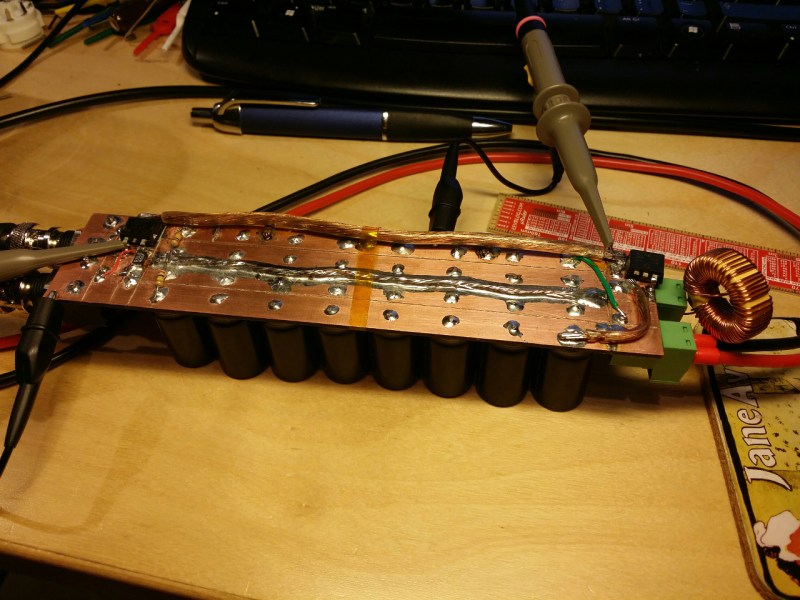
Knowing the limits of an inductor is very convenient when designing Switch Mode Power Supplies (SMPS) as an inadequate choice may result in very poor performances under high loads. [Kalle]’s tester simply consists in a N-Mosfet switching power through a load while a shunt allows current measurements. The saturation point is then found when the current going through the inductor suddenly peaks. As you can see from the picture above, 16 4700uF electrolytic caps are used to compensate for the sudden voltage drop when the Mosfet is activated. A video of the system in action is embedded after the break.


There is also ChaN’s version with a lot less capacitors here:
http://elm-chan.org/works/lchk/report.html
Why would the limits in a datasheet not be sufficient, especially since they may be given at a specific operating temperature?
For test purposes, observing the current going into an inductor on an oscilloscope would also work to identify when the inductor saturates, but this is a temperature dependent characteristic.
Is this just for testing unidentified parts for repurposing?
If you don’t know what the material is, or its maximum temperature rating, you are really just asking for thermal aging problems in indcutors used in switching power supplies.
Hey Evad!
Usually finding datasheets for repurposed cores is very difficult or impossible. Finding distributors for certain types of cores can also be difficult and/or expensive (such as very large cores or specialty items like planar transformer cores).
I personally wouldn’t put a repurposed core in anywhere where I would rely on the devices reliability so much that I would be worried about thermal aging.
I build a very similar device not to long ago, and it’s very usefull to determine some of the parameters from salvaged parts (for one-off hobby projects only, obviously), but also to check the design parameters for large, custom-made inductors, where you not only need to wind it, but need to create the desired airgap as well.
After initial testing, I did add a small opamp circuit to feed the derivative of the current into another channel of the scope (I was rather dissapointed to find my Tektronix DSO can’t display the derivatve of a channel). It is much easier to see the start of the saturation on this derivative channel than on the channel displaying the actual current. The coil used in the video saturates fairly abruptly, many coils have a much more gradual saturation characteristic, making it harder to see.
I’d like to see your design! I like the derivative plot idea.
I have seen sloppy datasheets that only listed the rated current without saying if it is a current limit due to I2R heating effect or a saturation current. If a vendor/seller doesn’t list them separately, you should else where. Better vendors even have models for parasitics etc.
Still it is useful to check the parts if they are bought off from ebay/China or from old power supply.
The saturation current is mostly dependent on the how much magnetic flux the material can contain. There might be a temperature component in that, but that’s not the only factor. The material can have a frequency loss component too. e.g. If you use iron core in a high frequency supply, the core material will heat up. If you have to worry about maximum temperature, then you are already using the wrong part.
I’m not sure what you mean by:
“If you have to worry about maximum temperature, then you are already using the wrong part.”
If your inductor core is hot enough (to burn your hands) have to worry about max temp, then you are already using the wrong part.
e.g. low frequency iron powder for high frequency or a lossy inductor intended for filtering and use it for switch mode supply. Or you are not using current mode PWM…
Or the inductor/transformer is just sized incorrectly. For example usually ferrite transformers are loss limited and not saturation limited so designing the transformer properly (including the winding material, type of Litz-wire used etc.) plays a big part.