In general, machining metal on a lathe or mill takes skill and patience as the accuracy of the cuts are important. To make those accurate cuts, it is important to know where the tool is located and how far it moves. For manual machines, the most basic method of determining position is by using graduated dials mounted on the hand cranks. Although these graduated dials can certainly be accurate, they may be difficult to see and they also require the operator to do math in their head on the fly with every full revolution of the dial. Another option would be a digital read out (DRO) which has an encoder mounted to the moving axes of the machine. This setup displays the exact position of the tool on an easy to read numeric display.
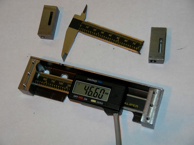
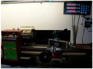
Professional DRO kits for mills and lathes can cost between a few hundred dollars to several thousand dollars. [Robert] has a lathe, wanted a DRO but didn’t want to shell out serious cash to get it. He built his own for super cheap in an extremely resourceful way…. using a Harbor Freight Digital Caliper. A housing was first fabricated so that the added equipment would not hinder the axis travel of the lathe. The caliper was then cut to length, installed in the housing and the entire assembly was then mounted to the lathe.
 It is totally reasonable to use the stock caliper display to read the positional information, however, even these cheap digital calipers have connections for the encoder output data, which can easily be read by a microcontroller. That means it is super simple to hook these low-cost digital calipers up to a display remotely located in a more convenient position.


Shouldn’t the title read “Yet another DRO”?
Don’t most lathes/mills have at least an order of magnitude greater accuracy than those cheapo calipers? The ones I have only have a resolution of 0.02mm and and an accuracy of about 0.05 – 0.1mm
Yes and no, theyre rated at 0.02mm in 150mm lengths but with a consistant operation pressure and no flex applied via the thumbscrew often achieve much much better than that anyway when gauged off against a standard as the inaccuracy comes from varying clamp pressures flexing the frame because of the thumb operating them, and if needs be you can always fall back to the dials or have got used to setting up a clock to measure travel which you will do anyway at install to sanity check its all ok.
What the dro capability does score bigtime with is it measures actual movement of the slides, on a older machine there will be some slop in the leadscrews, slideway play and other things introducing inaccuracies in comparison to the dial readings. I see my table shift during heavy machining very very rarely even though its locked in position sometimes and see the numbers change on the dro yet the dials haven’t moved because its still within the backlash of the screws.
So now I can correct it instead of spending hours machining extra features and making scrap anyway.
How much backlash do you have actually have? Most people (including precision ‘top end’ VMC companies a la HAAS) use recirculating balls in their bearing housings and a spring pre-load to effectively eliminate the slop. This is good for micro-tuning cross and top-slides for a 40 thou cut (or basically anything that you’d use a thou or tenths indicator on), but what are the common hacks to cover 60 inches of bed travel?
Slow day in the tip queue?
It’s also worth noting that those cheapo calipers can be used with either an Arduino or a Launchpad communicating with an Android device via Bluetooth or USB serial to turn that into a DRO using the following app and code: http://www.yuriystoys.com/p/android-dro.html
That’s what I’m going to do with one of the Chinese-made 7″ tablets I got from DealExtreme for under $40 in a half-off sale a while back.
Be careful about the spec of tablet you source for yuri’s project, he has some notes on his page what spec it has to have and some of the low end stuff does not have all of it.
Well, I’d already bought four 7″ tablets and an ‘Android TV’ stick from that sale at least six months before I’d heard of the Android DRO project. But the one I’m going to use seems to run the app just fine. At the time I tested it, the app didn’t yet support the cheap Chinese scales though, heh. Still haven’t gotten back to working on it.
I’ve got a mini-lathe AND mini-mill that could both use DROs. (And more than enough calipers, including a 12″ I got for $2.95 on Amazon because someone slipped a decimal place and had to honor the pricing error!)
Interesting, I’ve tinkered with this area a bit myself. I started off with a caliper mod the same as the op’s but I needed much longer scales.
So I bought a wixey table saw DRO replacement tape, some aluminium profile for a runner to bond it to and a read head housing from a block of nylon machined up. It takes the innards from the caliper heads which you can buy seperately minus the lcd screen. Actual length 50cm, perfect for smaller mills.
Hardware wise, I’ve tried the msh dro project and I have a YaDRO but that now struggles to cope with talking to the latest caliper heads that have come along (they often talk different protocols), but haven’t tried the Yuri one yet as I came into some funds and bought a glass scales and DRO kit from the thailand seller who has been fantastic after I broke one of the scales fitting it (PEBKAC… I mixed up Z and X axis scales on final final fitment and fitted the small one to the X and ran out of travel).
I’m working on a cnc mill at the moment but I may finish my saw tape dro and fit it the shaper, just for giggles :)
Oh hell yeah. Thanks for the leads on those companies. I went as far as to read the Mitutoyo data sheets where they described their caliper design and was going to get around to actually design and fab a clone for long, but as usual, someones done it for me!
Glass scales as in the capacitive copper was actually CVD’d onto glass rather than aluminum (presumabiy to limit flex?) Ben from Applied Science has a “DIY Gorilla glass” hack that’s useful without having to pay for borosilicate. His drop-testing unit was a little janky, but it proved effective.
I also read a paper (I want to say in Nature Methods?) where people took lasers (the same type that are used to micro-cut precision resistors to a specific path-length so your ohmic value is accurate to like 7 nines) and burnt in tons of micro-fractures into the surface of the glass, allowing for tensile loading. I don’t remember the actual numbers but I remember my reaction was “wow, great gains for a cheap method”.
I’ve done the same to my mini lathe, but this definitely looks a lot better!
Why put in all this time and effort but use a Harbor Freight Digital Caliper?
You would rather he cut up a more expensive caliper to find out he broke it in the process?
These sorts of DRO projects are *designed* for cheap Chinese calipers. What’s he supposed to use, a Mitutoyo? For that price, he might as well just do a CNC conversion!
You can get a beat up, old, used Mitutoyo for $50 or less. It’s sealed, and you don’t care that it’s got damaged ends if you are going to modify (remove) them anyway.
AvE tore down cheapos (he’s no stranger to precision grade-0 Mitutoyo’s or Starretts). The difference in design was 1: the cheapos kept their battery running 24/7 as to retain their position value, 2: the finish was shit (he had to deburr the metal himself), 3: no thumbwheel. The repeatability (precision) of the cheapos (out of the box at least, who knows how it will last over time—extended use might abrasively wear down materials leading to all sorts of problems) was more or less on par with the Mitutoyos.
All digi calipers work the similarly — as long as the sensor strip has evenly spaced teeth (http://wixey.com/fence/spareparts/index.html go to item 7003 – those ‘teeth’ are bits of copper that act as capacitive loading), is mounted straight to it’s platen, etc — you’re going to get accurate readings.
The difference you’re getting with the A+++ Japanese stuff is that you buy that unit and are 100% sure the quality control is just absolutely bang-on. Same with German gear. Fit and finish, absolutely always spot on. Huang-Tsu calipers are a crapshoot. Keith Fenner I think said he treats Chinese imports as “kits”, and expects there’ll be some finishing work to be done on any piece of gear he buys to get it into tolerance/working order…Take it apart, make sure everything is aligned right, bearings weren’t skimped out skimped out on, your loads are balanced, I think that’s pretty productive way of looking at things. Stefan Gotototententneberg and This Old Tony (both of whom are no strangers to working with sub-thou tolerances at their day job, it’d seem) have done similar tear downs/accuracy+precision analysis and then offered the DIY fixing methodology, allowing hobbyists such as I to buy cheapo Chinese 3 jaw’s for 150$ rather than a $1200 Rohm.
Because it puts the total cost at less than $20? If you want something more accurate and have money you would just buy a real dro.
Mahr Calipers are the best http://megadepot.com/catalog/testing-measuring-equipment/calipers-and-micrometers?search=caliper&sort=price#main (but the price is much more than $20)
With an error limit of .001″, I would hardly call them “the best”
Doing something similar myself. I tried caliper type scales on my machines but could never trust the readings. I’ve ended up using 2 micron magnetic encoders chips with an Arduino. Work in progress but nearly complete. Have a look… http://pcm52.com.
can these calipers be eazely connected to my expensive dro with glass scales on my mill? that way i could add dro to my lathe and use the same “dro” with all the features.