Several times in the last few weeks, I’ve heard people say, ‘this will be the last PCB I design in Eagle.’ That’s bad news for CadSoft, but if there’s one thing Eagle has done right, its their switch to an XML file format. Now anyone can write their own design tools for Eagle without mucking about with binary files.
Not all EDA softwares are created equally, and a lot of vendors use binary file formats as a way to keep their market share. Altium is one of the worst offenders, but by diving into the binary files it’s possible to reverse engineer these proprietary file formats into something nearly human-readable.
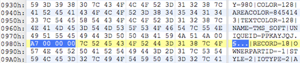
[dstanko.au]’s first step towards using an Altium file with his own tools was opening it up with a hex editor. Yeah, this is as raw as it can possibly get, but simply by scrolling through the file, he was able to find some interesting bits hanging around the file. It turns out, Altium uses something called a Compound Document File, similar to what Office uses for Word and PowerPoint files, to store all the information. Looking through the lens of this file format, [dstanko.au] found all the content was held in a stream called ‘FileHeader’, everything was an array of strings (yeah, everything is in text), and lines of text are separated by ‘|’ in name=value pairs.
With a little bit of code, [dstanko] managed to dump all these text records into a pseudo plain text format, then convert everything into JSON. You can check out all the code here.


Hey, can anyone explain why are people saying: “this will be the last PCB I design in Eagle.”? Is there any other freeware solution that can match Eagle?
Please, read the following comments. You will find the answer.
kicad, IMO its just as horrid as eagle
There is nothing as horrid as KiCAD. The user interface of KiCAD is the worst design I have ever used in any application. Ever. So much promise lost in a sea of impossibly unintuitive user design.
That’s right, Altium is frustrating most of the time, it is an enormous and architectural piece of shit. The more time i spent with Altium the more i dream about those days in the college with Eagle. I’m migrating to Eagle right now, and many of my collegues too.
I’m the opposite, I started and pretty much mastered Eagle, but it left me being incapable of really pushing the envelope with High-Speed design, intregrated simulation and very complex commercial projects that are done with larger team or with tight integration with mechanical and product design teams.
So I jumped to Altium.
And rest of this might sound like Altium advertisement, but it’s based on my personal experiences using it.
It’s not perfect by any means. it’s user interface complicated compared to Eagle, and can be very tedious when it forces you to follow certain (at first hand convoluted) practices to update data and board and back/forward annotate.
But those practices are in place exactly for a reason of putting checks in place to prevent you from ignoring DRC/ERC warnings or making a change to a component/board/anything in the vault or the design without it being checked, verified, accepted and reported.. And if it does mess up something, one can point to a reports that were filed by the software that who made the change, when it was made and who checked and accepted it to be made and what was the change.
Need to follow exact IPC/JEDEC-standards on your footprints, naming schemes, pads? Altium gives you tools to do that properly.
Need simulations of high speed signals based on your board layout? Altium gives you tools to do that.
Need someone to tweak the component values on DC/DC-converter using simulations while you continue the design on the processors interconnects? Altium allows you to do that with good integration.
When complexity of the projects increase, schedule tightens and the price tag on screw ups is high, one’s quite happy about this functionality no matter how it might feel like it’s “bogging you down” at first. It’s protecting you from shooting yourself in the foot even if you’re just one or two man team.
In larger teams it’s essential.
Eagle can’t do serious high-speed stuff, rigid flex designs or very tight mechanical integration. The libraries can’t be verified and ensured that their validity is controlled throughout the design and from a central location since Eagle doesn’t come with proper database integration.
One can’t really force/imply design intent from the schematic to the layout by using rule directives for high speed interconnects or 50-ohm lines or what ever.
Etc.
It’s all about what one wants to do.
One off quick project? Very simple project with one man team? Sure, Eagle is lighter in that sense.
But until KiCad really has what it takes to be serious competitor in the commercial sector, There’s very little to keep one with Eagle.
Can anyone tell me the reason why people will not use eagle again ? Any news that I missed ?
krater, I don’t know for sure. I think people were using Eagle just because there wasn’t a better Free and Open Source option. Now KiCAD fits this gap. Test a recent KiCAD version and you will know why people are moving to it ;-)
How are the parts libraries?
Yes,that was the reason why I everytime used Eagle. So this is the critical question. I like the user interface of eagle, so thats no point for me.
Actually Eagle parts libraries quality aren’t that great… Parts are very out of date. Really could use some major clean up and better organization.
You really have to check the “free” libraries as some have wrong pin outs and some even have wrong spacings. I found 3-4 of those in my project. Unfortunately one of after the PCB was made and I would have think that a rev 3 of the library would have fixed that mistake for a common part!? My fault for trusting someone else.
You also have to know what they are designed for – home made PCB vs board house as the pad sizes can be very different. They are a good starting point even when you have to hand check all the new ones and fix them. Keep your trusted library in a separate directory than the ones that come with the package.
Ok ok, the Eagle libraries are a little bit outdated, and some free libs found in the web are not 100% correct.
BUT this doesn’t answer the question. How good are the kicad libs ? And, are they existent ?
I do not use symbols that doesn’t show their power/ground pins explicitly as I like to plan for the proper number of decoupling caps and work with multiple power rails. Not doing that is asking for trouble if you are doing any serious designs.
Not care about KiCAD libraries. KiCAD go against my belief in parts should be tied to their footprints. They can do whatever they want, but meh for me.
I’ve used Kicad professionally for 7 years now, and have designed probably a couple dozen boards with it, including one four-layer design with components on both sides. I’ve used the supplied libraries as starting points to create my own custom schematic symbol and footprint libraries – these days I very seldom use the supplied libraries. With information supplied by parts manufacturers, along with land pattern recommendations available via a Google search, it’s pretty easy to create your own, and your libraries are as good as you want to make them.
Kicad is quirky, but very full-featured provided you don’t need simulation. Plus, its files are all plaintext and pretty easy to read; I’ve modified them with a text editor and had the PCB’s produced by professional fabricators with no problem. Also, it comes in Windoze and Linux versions, and all of the library, schematic, and footprint files can be moved back and forth between platforms without needing any conversion process.
How is the forward/backward annotation?
Hi daid303,
Page 28: http://oregonembedded.com/tools/Getting_Started_in_KiCad.pdf
Thanks for the answer. I will test it when I have spare time.
Lack of dynamic DRC (you can route everywhere everything)
No dynamic plane
Crappy interface with 100s click to route a wire
Esoteric interface to set custom clearance between class
….
I can give you a long list of features that really miss when using eagle.
Not to mention the new licensing restriction in the 7.x.x builds.
Some really liked eagle because they could buy a single license, install it on multiple computers (but only run a single instance at a time). From what I heard, these single-user license are now machine-restricted. CADSoft requires you to purchase a license per computer you install it on.
If it’s true it deserves a TROLOLOLOL :D
For same price range Diptrace is a little better, and since 2008 kicad can do everything eagle does with a real interface etc…
I don’t know why people stay on eagle, if cadsoft can’t evolve quickly they’ll suffer in few years.
We removed the new licensing system a month after the release of V7. We’re back to our old licensing mechanism which allows you to install EAGLE on as many computers as you own as long as your the only user.
If there’s anything I can help with please feel free to contact me support@cadsoftusa.com.
Jorge Garcia
Cadsoft Support
That is no longer true with 7.1 Eagle. Users rebelled. Cadsoft backed off the new license model. It’s the same as 6.x now.
Why Kicad must be same as Eagle? Every option same.. RLY? Something like LibreOffice must be same as MS Word, because users don’t know anything only MSoffice. Same in this EDA corner.
Kicad isn’t perfect, that’s right. But complaining for what this program lack another program features isn’t good point. In that manner you you would buy CadSoft license or other propietary SW for bunch of money and remove Kicad’s interface headache.
So, overall question about OSS developing. Whether OSS must be same as other propietary SW? By its features, functions, third party plugins etc.
P.S. Even CERN developing Kicad to imrpove it: http://www.ohwr.org/projects/cern-kicad/wiki/WorkPackages
Not sure about what comment you’re answering too here
Actually to your’s comment (http://hackaday.com/2014/10/15/reverse-engineering-altium-files/#comment-1999374) Long quotations are difficult to read in this HaD comment system.
Again, does OSS developers have to implement features and functions like there is in propietary SW a.k.a copy another SW functions. Thus then users will go itself on Kicad.. Whether it is a necessity to do that?
I’m not a SW developer, but I use Kicad for my DIY purposes a long time. Of course, there is minor cons, but mostly fulfils my needs.
My comment was about eagle and not kicad. I use kicad since 2008 and even used it professionally ;)
article blocked by altium law makers in 3…
also pls use kicad
Nice! Many developers are moving to KiCAD thanks its recent features and improvements. It will be nice to import Altium design directly in KiCAD.
Altium supports an ASCII format, all the way from the old Protel 2.8 days. I’m using the older Summer ’09 (so somebody else may need to confirm this if it’s still functional), and am able to save my files “Advanced Schematic Ascii” or “PCB Ascii File” that are very much human-readable.
So although it’s nice to be able to crack the binary, it can be cross-referenced with a legit ascii dump for verification.
–Schematic dump sample—
|RECORD=6|OWNERINDEX=247|ISNOTACCESIBLE=T|INDEXINSHEET=2|OWNERPARTID=1|LINEWIDTH=1|COLOR=16711680|LOCATIONCOUNT=5|X1=610|Y1=785|X2=610|Y2=765|X3=630|Y3=755|X4=630|Y4=775|X5=610|Y5=785
|RECORD=41|OWNERINDEX=247|INDEXINSHEET=3|OWNERPARTID=-1|LOCATION.X=609|LOCATION.Y=792|COLOR=8388608|FONTID=1|ISHIDDEN=T|TEXT=40 Ohm @ 100MHz|ISHIDDEN=T|NAME=Impedance @ Frequency|UNIQUEID=CXDYJEUA
–PCB dump example (for a pad location)–
|RECORD=Pad|NET=2|COMPONENT=1|INDEXFORSAVE=15|SELECTION=FALSE|LAYER=MULTILAYER|LOCKED=FALSE|POLYGONOUTLINE=FALSE|USERROUTED=TRUE|UNIONINDEX=0|NAME=2|X=455mil|Y=1232mil|XSIZE=125mil|YSIZE=125mil|SHAPE=RECTANGLE|HOLESIZE=35mil|ROTATION= 9.00000000000000E+0001|PLATED=TRUE|DAISYCHAIN=Load|CCSV=1|CPLV=1|CCWV=1|CENV=1|CAGV=1|CPEV=1|CSEV=1|CPCV=1|CPRV=1|CCS=Relief|CPL=0|CCW=10mil|CEN=4|CAG=10mil|CPE=0mil|CSE=4mil|CPC=20mil|CPR=20mil|PADMODE=0|SWAPID_PAD=|SWAPID_GATE=|&|0|SWAPPEDPADNAME=|GATEID=0|OVERRIDEWITHV6_6SHAPES=FALSE|DRILLTYPE=0|HOLETYPE=0|HOLEWIDTH=0mil|HOLEROTATION= 0.00000000000000E+0000|PADXOFFSET0=0mil|PADYOFFSET0=0mil|PADXOFFSET1=0mil|PADYOFFSET1=0mil|PADXOFFSET2=0mil|PADYOFFSET2=0mil|PADXOFFSET3=0mil|PADYOFFSET3=0mil|PADXOFFSET4=0mil|PADYOFFSET4=0mil|PADXOFFSET5=0mil|PADYOFFSET5=0mil|PADXOFFSET6=0mil|PADYOFFSET6=0mil|PADXOFFSET7=0mil|PADYOFFSET7=0mil|PADXOFFSET8=0mil|PADYOFFSET8=0mil|PADXOFFSET9=0mil|PADYOFFSET9=0mil|PADXOFFSET10=0mil|PADYOFFSET10=0mil|PADXOFFSET11=0mil|PADYOFFSET11=0mil|PADXOFFSET12=0mil|PADYOFFSET12=0mil|PADXOFFSET13=0mil|PADYOFFSET13=0mil|PADXOFFSET14=0mil|PADYOFFSET14=0mil|PADXOFFSET15=0mil|PADYOFFSET15=0mil|PADXOFFSET16=0mil|PADYOFFSET16=0mil|PADXOFFSET17=0mil|PADYOFFSET17=0mil|PADXOFFSET18=0mil|PADYOFFSET18=0mil|PADXOFFSET19=0mil|PADYOFFSET19=0mil|PADXOFFSET20=0mil|PADYOFFSET20=0mil|PADXOFFSET21=0mil|PADYOFFSET21=0mil|PADXOFFSET22=0mil|PADYOFFSET22=0mil|PADXOFFSET23=0mil|PADYOFFSET23=0mil|PADXOFFSET24=0mil|PADYOFFSET24=0mil|PADXOFFSET25=0mil|PADYOFFSET25=0mil|PADXOFFSET26=0mil|PADYOFFSET26=0mil|PADXOFFSET27=0mil|PADYOFFSET27=0mil|PADXOFFSET28=0mil|PADYOFFSET28=0mil|PADXOFFSET29=0mil|PADYOFFSET29=0mil|PADXOFFSET30=0mil|PADYOFFSET30=0mil|PADXOFFSET31=0mil|PADYOFFSET31=0mil|PADJUMPERID=0
The idea behind the talk was not to necessarily go for Altium, but to provide tools and methodology to people that need to do these kind of things – you know that stuff about teaching people to fish…
The idea with the talk was not to go after Altium Designer file format (or any other, for that matter) but to give people the skill to do it if they find the need. You know that stuff about teaching people to fish…
I reversed engineered their old commercial gone Freeware DOS package EasyTrax. (more of a layout/paint program as there wasn’t even a schematic capture.) That took almost no time. It was in binary format. Never heard of XML.
I wrote a easytrax to Windows Meta file and DXF filter for it and used it quite a bit to do board planning at one place as the layout tool and CAD tool was not allowed to be used outside of the layout group.
I agree with the other comment about XML not being the best format for human editing. If anyone that has done a compiler writing course and wrote a parsing program in C would have come up with a better file format for humans. Even the old Window .ini format was easy to understand and edit by human.
The ASCII File option is still available as of 14.3.15.
Altium 14 supports Ascii format save.
XML is better for editing the binary, but it does baffle me why its always chosen over, say, JSON.
It takes up more space and is harder to read :?
Does the “JS” part of JSON just scared people off from using it as a human read/editable data format?
Comparison of formats:
http://en.wikipedia.org/wiki/JSON#Samples
[/old rant sorry – I just have written a huge amount of xml in my life by now and wish most of it was nicer to edit by hand]
Amen brother!
It’s also worth noting that Altium gives you the ability to export into both ASCII and Binary file formats. It might help to look at an ASCII format file in order to better understand the binary files
I’ve written parsers for the ASCII files at work (in order to mass-rename designators and nets, and generate new UniqueIDs for copy/paste), the structure is fairly easy to understand.
One gotcha is that strings such as part comments, designators or net names, are stored as text encapsulated in quotes in one place, but then they’re also stored elsewhere as comma delimited ASCII values… And you have to change both for Altium not to catch fire.
The “binary” schematic format in Altium is just plain text + some fonts/graphics wrapped in a compound document file. On the contrary, PCB files contain also pure binary records that may be a bit harder to understand.
PS. If you’re trying to write an Altium import plugin for Kicad, please contact me, I may have some additional info.
Thanks for your feedback. I’ve been using Traxmaker/Protel/Altium for over 15 years now. Helping out with KiCad is very much on my list of ‘shit to do’, but I’ve been getting railed pretty hard with both work and studies. I wish I could find the time to assist in writing an importer.
If I do find the time, you bet that it’d be for KiCad.
Yes! I love this work, kudos so far. I have taken a look at the file format a couple of times. It would be nice to fully RE it so we can make new & novel applications. Don’t see the point in closed file formats – why not let your customers extend value to your software for free? Anyways, FWIW, the files can also be opened in a Zip program (Tested w/ 7zip). Not sure if this tidbit helps out in any way.
Here’s a screenshot of a PCB library file:
http://i.imgur.com/Ek8fDNR.png
Actually, looking into it more, seems like opening Compound Doc Files is a feature of 7Zip. So this doesn’t really help anyone. Ooops!
Wow, I was not aware of that – probably because I stopped using Windows a while back! Thanks!
Somehow I imagine users saying, “this will be the last PCB I design in Eagle,” are intending to switch to Altium, Mentor, etc – not KiCad. If you’ve used Eagle extensively in the past, KiCad is a downgrade. I keep trying, but always give up missing core features in Eagle that even Zuken doesn’t have. But feel free to dismiss my opinion as uneducated and flame away…
CadSoft didn’t do themselves any favors with 7.x however. The hierarchical design is a disaster, the auto-router changes are meaningless, and the license scare has soured the milk somewhat.
I’m still waiting for my automatic parallel trace-length router, controlled impedance router (diff pairs), signal integrity simulator, and a few other features out of a free or low cost EDA tool.
I’m just curious, what do you mean by an automatic parallel-length router? I don’t remember Eagle having such a feature, it’s not the same price range as Mentor/Cadence/Zuken…
We are working on diff pairs and matched length traces in Kicad, it should be available in the next stable release.
Regards,
Tom
KiCAD needs an easier to use copy – paste routine before anything else!
The clunky GUI is a bigger barrier to entry for new users than anything else.
In general GUI is one of the weakest part of open source software. Seems like that is often an after thought that someone kludge it on a command line / scripts. GUI is what the user see and work with and that should be driving the code behind it not the other way around. Also a non-native GUI to the OS platform is not user friendly.
I played with the precompiled code and it throws a big error and crashed because it wasn’t set up. Kind of silly when you don’t have an installer. Eagle comes with an installer and when you don’t have the directory structure setup or want the default paths, it ask you what the paths are instead of crashing. I think I have only seen Eagle crashed may be a handful of times.
in the newest version of eagle, there is a parallel length routing function. Before i really missed that feature.
All the places I worked for use an external auto router add-on to the layout program. Similarly for SI which is done by an external package. The built-in stuff from the EDA house aren’t that great.
Not sure parallel trace length router is either. I know of more advanced package that allow routing rules that specifies the max length that traces can be in parallel to limit coupling (SI reason). Is it a router that is specialized to route memory banks that have parallel bus?
Eagle 6.x diff pair routing is a joke. :(
Could you elaborate on the diff pair routing being a “joke”? What would you like to see? How can it be improved?
Suggestions are very important for us at Cadsoft so I would be interested in hearing your opinion. The same applies to anyone on this thread.
Best Regards,
Jorge Garcia
Cadsoft Support
OK – here’s a suggestion. How about something in between the cheapo $69 version and the next step up? Say, a slightly larger board and 4 layers?
Hi JimBob,
It sounds like you’re referring to the Hobbyist edition, $169.00 6 layers 160mm x 100mm(approx 6.25 x 4 in). This is a non-commercial license.
Now if the suggestion is commercial version between light and standard then it’s duly noted and thank you for your suggestion.
Best Regards,
Jorge Garcia
First off – the diff pair hand routing cannot be turned with a simple click. It takes quite a bit of space to make a turn (vs hand routing), so I have to pretty much hand drag the traces afterwards. I navigation part is painful as you lose control on when you want to make a turn. In general it is more hand re-routing/clean up work. While this is not how it works, I would like to see the option of hand route one side of a diff track and let the router work on its partner.
Also could be better length report. Sometimes it counts the length of one segment of a multidrop diff track and sometime it counts the whole thing. May be simply highlight the segment it is reporting? For the user, sometimes being able to select a segment or the entire bus is useful too because you want to length match the segments drops too. It is also more useful to have different ways of reading the diff pair length – having percentage is meaningless. I also want to see track difference in mils or in ns/ps (propagation delay).
On the other hand, it does maintain diff spacing even for 45 degrees rotated tracks which can be harder to hand route. (Due to basic geometry, your 5 mil grid for spacing vertical/horizontal tracks would not get you 5 mil separation for 45 degrees tracks.)
^ diff track cannot be turned off with a simple click
Esc key or select the next command you want to work with. Please ignore the first sentence of my post.
Thanks again for your feedback.
Best Regards,
Jorge Garcia
It takes two clicks, click on the ROUTE command and then click on one of the members of the Diff pair. :)
When you mention the space to turn, your referring to the possibility of the traces running over each other when you turn. Is this correct?
The length reporting by default reports complete lengths of the signals relative to the longest one(that’s where the percentage comes into play, the max length is also displayed). If you hold the ctrl key when you click with the meander command you can get the length of specific segment, ctrl+shift will give you the length of multiple segments.
I like the idea of ns/ps being displayed, being able to specify an overall length in units of time would be interesting.
Thanks for your feedback, and correct me if I misunderstood what you mentioned about turning.
Best Regards,
Jorge Garcia
It seems to want a few times more clearance than actually needed when you want the tracks to turn. Doesn’t work too well when you board is very tight. I know there is space because I can hand route it and I also managed that after it failed to route. It is like herding cats – it turns when it want to not when you want to. Doesn’t exactly turn on a dime and it is not good enough to replace my hand routing..
>If you hold the ctrl key when you click with the meander command you can get the length of specific segment
I can’t name the specifics, but I ran into cases where I had to part a diff track into a resistor pack. So one signal made a pass through to a pad (on the edge of the package and the other one enter the pad 2 and exited at 90 degrees two 45 degrees turns) escaping in the gap under the package. The length reports was different for the two where one was the entire trace and the other was from the pad. I had to manually add the track lengths. I would rather Control-select the segments (if that’s possible) and get a length report.
Also I can see cases where if I make a stub and/or a via to connect multidrop diff pair (e.g. BLVDS), it is still handy to get per segment length as well as overall length to that point.
Yeah. Pretty much the length matching for single ended tracks are tied to timing skews budgets, and diff tracks( eye opening for diff track too). There are data to clock skews for setup/clock to data time budget. Once again everything is timing driven.
Not much point know the percentage. Knowing that the track skews are 100ps is a lot more useful than just a 110%. That means very different signal qualities when your tracks are 100 mils or 10 inches.
I was referring to balanced routing of a group of parallel traces like memory DQ’s and DQS strobes. I wasn’t aware of anything that would specifically route a set of related traces for equal length and nothing else on the board.
Auto-routers in general are very poor and do not consider any SI issues such as ground return impedance, etc – and Eagle’s is no exception. However routing nets with specific requirements is something useful.
I find Eagle’s interface to be super annoying, but I have kept it around for making low count boards because I like the pcb-gcode ULP for isolation routing.
Anyone know of a better option for this?
I think you can set separation between net classes. So one class of net for your primary circuit and different set for the secondary side that needs to separated. The DRC and autorouter would be able to use that.
For a quick and dirty way, draw a thick track of the minimum separation between the area before routing and remember to remove it afterwards. (I use document layer for gauging the track spacing e.g. for 45 degrees lines.) A track in the copper layers would stop the autorouter from routing tracks that are too close.
I appreciate the answer, but that’s not really what I’m talking about. Probably my fault, because in this sense, I mean routing out the copper between traces on a CNC mill. the PCB-GCode ULP offsets the traces from layout based on your settings, and generates GCode to run the machine. There’s software I like better, but I haven’t discovered any that will let me mill my own boards.
I wonder why no one here speaks about DesignSpark PCB?
http://www.rs-online.com/designspark/electronics/eng/page/designspark-pcb-home-page
It costs nothing, it has a 3D view, it supports foreward/backward annotation between PCB an schematic …
And the userinterface makes a better impression for me, then the “bird”.
I made some PCBs with Eagle, but I hate using the librarys – especially to draw or modify or copy parts with it. I never understood the process completely. That’s the reason why I gave DesignSpark a chance. As far as I can see, it has mightier features then KiCAD.
The deal why it is “free” (but you have to register it) is, because it exports a part list ready to buy the parts from the distributor RS Components.
But there is no need to buy the parts there, you can buy them elsewhere. Off course, RS hopes …
I think this is a fair deal an a garant, that the software will be developed further, from this company.
KiCAD, in spite of that, can die any day I think, if the author looses his motivation to work on it.
So, what’s the problem with DesignSpark?
I use Designspark for boards that I will send out for fab. It’s great. I just doesn’t support milling my own PCBs (that I know of).
@Stefan: “KiCAD, in spite of that, can die any day I think, if the author looses his motivation to work on it.”
For what reason this assumption is made? Only on “loosing motivation”? Can you prove your point more broadly? Not only relying on “can die any day”.
I said it can die any day, because I have experienced such a sad thing.
For many years I used the great programm “Scooter-PCB” from HK-Datentechnik:
http://hk-datentechnik.de/scooter-pcb.php
It was (and is!) a really great program and the author is a genius!
(Look at the background of my website: http://www.EDV-Dompteur.de – all PBCs was made with Scooter!)
But he was the one and only person behind the program. Scooter-PCB was cheap (today it is free!) and it was never as well known as Eagle. Mr. Kahlert supportet it for 15 years, but from what he got for it, it wasn’t possible to live from. Someday, 10 or more years ago, he stopped working on it.
I made big an complex PCBs with Scooter, and in my opinion, the features wasn’t behind Eagle. But it was a pure 2D PCB-programm, without a module for making schematics. One have had to use OrCAD or an other programm for drawing schematics and there was no chance to get 3D.
Scooter was a one-person-show. It has died …
As far as I understand, KiCAD also is a “one-man-show” and it brings no money for the author. That’s a bad combination – for the users!
That’s the reason why I would have an uneasy feeling, to use it.
Over the years I drawed hundred of library parts for Scooter-PCB. A lot of work.
Now I have to use a new PCB-programm and all my current work is for the trash.
OK, even today I use it, here and there, because I don’n know an other programm with such a great “look and fell” who brings such fast results like Scooter.
In cases where is no need for a schematic or for 3D, I really love it.
I think, KiCAD is a comparable case. A nice product, easy to use, but the author is only one single person who can’t live from it. So it can die any day. That’s only my impression (it may be wrong).
In case of DesignSpark: There is a team and a company behind it. The company hopes to collect money. Not from selling the programm itself (it’s free!), but from selling the components in the layout. Why should it die?
In my opinion, it plays in the same Liga as Eagle. It even has some nice benefits, Eagle hasn’t. And it has (in my opinon) a much better look and feel.
But I’m a Newbie with it. Because of that I was asking about DesignSpark. Maybe there are good reasons better not to use it.
Wenn ich habe deiner Seite gelest, möchte auf deutsch sprechen, aber must wir auf englisch sprechen, dass die leser wurde verstand uns. Entschuldigung Sie bitte, aber Englisch ist hier hauptsprache.
Interesting opinion.I don’t want to underestimate one man’s work, but “one man army” today isn’t very successful style. Or just his selected business model is wrong over long term.
That’s ok, that “Scooter-PCB” is free. But you never see a implementation and source code. I don’t understand why people prefer reverse engineering, when you can just grab code from Git and modify by itself by no restrictions (under GPL).
I think so, that actually in EULA is line, where writen, that reverse engineering is prohibited. But we live in real world, not imaginary where people strictly follow propietary SW license. There’s cracks, disassembly, reverse engineering.. and internet :))
About Kicad. Kicad isn’t “one man project”. You can see here how are many contributors: https://launchpad.net/kicad/+topcontributors
If you talk about money.. Opensource SW community works by other principle – mostly donation. Thus you can donate, that maintain a motivation for developers or you can itself become a contributor. I see many opportunities for power users and standart users working together.
As I’ve said above, event CERN is Kicad’s contributor. Actually I don’t know everething about that, how different contibutors versions will be used.
Kicad isn’t that unpopular how you imagine. Here’s few examples: http://numato.cc/content/kicad-more-complex-boards-our-experiment-spartan6-csg225
http://www.kicadlib.org/Kicad_related_links.html
http://hackaday.com/2012/08/16/toorcamp-milling-pcbs-with-kicad/
http://flickrhivemind.net/Tags/kicad/Interesting
http://embeddedprogrammer.blogspot.com/2012/06/3d-and-footprint-libraries-for-kicad.html
http://www.bigmessowires.com/2010/05/03/eagle-vs-kicad/
http://hackaday.com/2012/02/17/kicad-symbol-generating-script-shows-promise/
http://hackaday.com/2013/10/15/creating-irregular-board-outlines-in-kicad/
http://library.oshec.org/ (Converted Eagle libraries for Kicad)
http://smisioto.no-ip.org/elettronica/kicad/kicad-en.htm
So, seeing many successful projects with Kicad I don’t think, that Kicad dies one day. And its strength is in modifying how you want to, and no need for pain i a butt when reverse engeneering something. Kicad has a lot potential ant there’s no need for stick with one product in life.
Very good weblinks, thank you!
OK, I was wrong, as I thougt KiCAD would be a one-person-project.
For me there is only one big problem left, opposite to SparkFun-PCB: SparkFun supports forward/backward annotation between layout an schematic.
That means: Changings in the layout acting back to the schematic.
Eagle and KiCAD can’t do that, but SparkFun can.
This feature saves so much time and frust!
Because of your excellent posting I will have a clooser look now, to both: KiCAD and SparkFun. But my time with Eagle is over.
You’re welcome!
Actually someone above in discussion mentioned about forward/backward annotation: http://hackaday.com/2014/10/15/reverse-engineering-altium-files/#comment-1999404
In Kicad components and footprints are seperated. You can’t do backward annotation because your workflow base starts from Eeschema, where changes are made and then newly generated netlist is imported to Cvpcb to change modules footprints and then in Pcbnew to reroute layout. Or just you can change only footprints in Cvpcb and then import to Pcbnew new netlist.
If You decide to look in Kicad more, here’s a concetrated link that I found, when explored Kicad functions and tutorials: http://www.meatandnetworking.com/w/Kicad_Resources
So, if You find Kicad helpful to your wishes, i wish you good projects with Kicad!
What about a commercial low cost package like Autotrax DEX?
http://kov.com/
http://www.schematic-software.com/Features
Excellent work! I can confirm this piece of code works like a charm with Altium 16 (licensed version)
Brilliant!
I can confirm the java app to work for licensed Altium 16 files. Kudos!