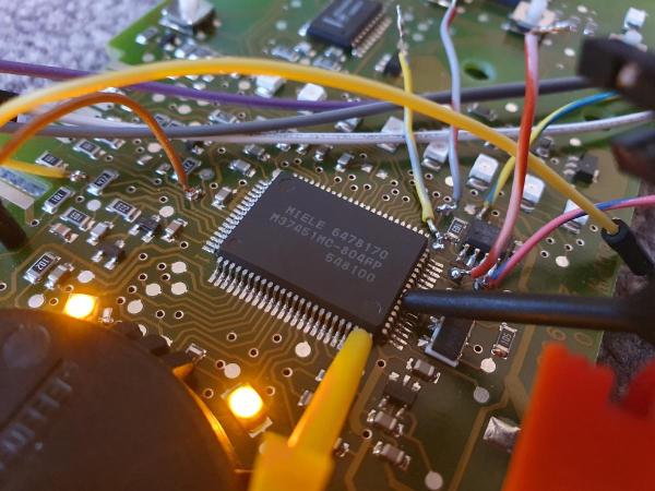
Reverse Engineering A Fancy Disposable Vape

Many readers will be aware of the trend for disposable vapes, and how harvesting them for lithium-ion batteries has become a popular pastime in our community. We’re all used to the slim ones about the size of a marker pen, but it’s a surprise to find that they also come in larger sizes equipped with colour LCD screens. [Jason Gin] received one of this type of vape, and set about reverse engineering it.

What he found inside alongside the lithium-ion cell (we love his use of the term ” street lithium” by the way) was an ARM Cortex M0 microcontroller, 1 MB of flash, and that 80×160 display. Some investigation revealed this last part to have an ST7735S controller with an SPI interface. He turned his attention to the flash, which was filled with the bitmaps for the display. Seeing an opportunity there, this lead to the creation of a Windows 95 theme for the device.

Finally, the microcontroller turned out to be accessible with programming tools, with an unprotected firmware. The reverse engineering effort is ongoing, but we hope the result is a small dev board that will at least save some of the from being e-waste. If you’re curious, all the tools used are in a GitHub repository.

Meanwhile, we’ve looked at street lithium harvesting before.

Thanks [DeadFishOnTheLanding] for the tip!

Reverse Engineering The Quansheng Hardware

In the world of cheap amateur radio transceivers, the Quansheng UV-K5 can’t be beaten for hackability. But pretty much every hack we’ve seen so far focuses on the firmware. What about the hardware?

To answer that question, [mentalDetector] enlisted the help of a few compatriots and vivisected a UV-K5 to find out what makes it tick. The result is a complete hardware description of the radio, including schematics, PCB design files, and 3D renders. The radio was a malfunctioning unit that was donated by collaborator [Manuel], who desoldered all the components and measured which ones he could to determine specific values. The parts that resisted his investigations got bundled up along with the stripped PCB to [mentalDetector], who used a NanoVNA to characterize them as well as possible. Documentation was up to collaborator [Ludwich], who also made tweaks to the schematic as it developed.

PCB reverse engineering was pretty intense. The front and back of the PCB — rev 1.4, for those playing along at home — were carefully photographed before getting the sandpaper treatment to reveal the inner two layers. The result was a series of high-resolution photos that were aligned to show which traces connected to which components or vias, which led to the finished schematics. There are still a few unknown components, The schematic has a few components crossed out, mostly capacitors by the look of it, representing unpopulated pads on the PCB.

Hats off to the team for the work here, which should make hardware hacks on the radio much easier. We’re looking forward to what’ll come from this effort. If you want to check out some of the firmware exploits that have already been accomplished on this radio, check out the Trojan Pong upgrade, or the possibilities of band expansion. We’ve also seen a mixed hardware-firmware upgrade that really shines.

Ancient Cable Modem Reveals Its RF Secrets

Most reverse engineering projects we see around here have some sort of practical endpoint in mind. Usually, but not always. Reverse-engineering a 40-year-old cable modem probably serves no practical end, except for the simple pleasure of understanding how 1980s tech worked.

You’ll be forgiven if the NABU Network, the source of the modem [Jared Boone] tears into, sounds unfamiliar; it only existed from 1982 to 1985 and primarily operated in Ottawa, Canada. It’s pretty interesting though, especially the Z80-based computer that was part of the package. The modem itself is a boxy affair bearing all the hallmarks of 1980s tech. [Jared]’s inspection revealed a power supply with a big transformer, a main logic board, and a mysterious shielded section with all the RF circuits, which is the focus of the video below.

Using a signal generator, a spectrum analyzer, and an oscilloscope, not to mention the PCB silkscreen and component markings, [Jared] built a block diagram of the circuit and determined the important frequencies for things like the local oscillator. He worked through the RF section, discovering what each compartment does, with the most interesting one probably being the quadrature demodulator. But things took a decidedly digital twist in the last compartment, where the modulated RF is turned into digital data with a couple of 7400-series chips, some comparators, and a crystal oscillator.

This tour of 80s tech and the methods [Jared] used to figure out what’s going on in this box were pretty impressive. There’s more to come on this project, including recreating the original signal with SDRs. In the mean time, if this put you in the mood for other videotext systems of the 80s, you might enjoy this Minitel terminal teardown.

Continue reading “Ancient Cable Modem Reveals Its RF Secrets”

Hacked Oscilloscope Plays Breakout, Hints At More

You know things are getting real when the Dremel is one of the first tools you turn to after unboxing your new oscilloscope. But when your goal is to hack the scope to play Breakout, sometimes plastic needs to be sacrificed.

Granted, the scope in question, a Fnirsi DSO152, only cost [David Given] from Poking Technology a couple of bucks. And while the little instrument really isn’t that bad inside, it’s limited to a single channel and 200 kHz of bandwidth, so it’s not exactly lab quality. The big attractions for [David] were the CH32F103 microcontroller and the prominent debug port inside, not to mention the large color LCD panel.

[David]’s attack began with the debug port and case mods to allow access, but quickly ground to a halt when he accidentally erased the original firmware. But no matter — tracing out the pins is always an option. [David] made that easier by overlaying large photos of both sides of the board, which let him figure out which buttons went to which pins, and mapping for the display’s parallel interface. He didn’t mess with any of the analog stuff except to create a quick “Hello, oscilloscope!” program to output a square wave to the calibration pin. He did, however, create a display driver and port a game of breakout to the scope — video after the hop.

We’ve been seeing a lot of buzz around the CH32xx MCUs lately; seeing it start to show up in retail products is perhaps a leading indicator of where the cheap RISC chips are headed. We’ve seen a few interesting hacks with them, but we’ve also heard tell they can be hard to come by. Maybe getting one of these scopes to tear apart can fix that, though.

Continue reading “Hacked Oscilloscope Plays Breakout, Hints At More”

Human-Interfacing Devices: HID Over I2C

In the previous two HID articles, we talked about stealing HID descriptors, learned about a number of cool tools you can use for HID hacking on Linux, and created a touchscreen device. This time, let’s talk about an underappreciated HID standard, but one that you might be using right now as you’re reading this article – I2C-HID, or HID over I2C.

HID as a protocol can be tunneled over many different channels. If you’ve used a Bluetooth keyboard, for instance, you’ve used tunneled HID. For about ten years now, I2C-HID has been heavily present in laptop space, it was initially used in touchpads, later in touchscreens, and now also in sensor hubs. Yes, you can expose sensor data over HID, and if you have a clamshell (foldable) laptop, that’s how the rotation-determining accelerometer exposes its data to your OS.

This capacitive touchscreen controller is not I2C-HID, even though it is I2C. By [Raymond Spekking], CC-BY-SA 4.0
Not every I2C-connected input device is I2C-HID. For instance, if you’ve seen older tablets with I2C-connected touchscreens, don’t get your hopes up, as they likely don’t use HID – it’s just a complex-ish I2C device, with enough proprietary registers and commands to drive you crazy even if your logic analysis skills are on point. I2C-HID is nowhere near that, and it’s also way better than PS/2 we used before – an x86-only interface with limited capabilities, already almost extinct from even x86 boards, and further threatened in this increasingly RISCy world. I2C-HID is low-power, especially compared to USB, as capable as HID goes, compatible with existing HID software, and ubiquitous enough that you surely already have an I2C port available on your SBC.

In modern world of input devices, I2C-HID is spreading, and the coolest thing is that it’s standardized. The standardization means a lot of great things for us hackers. For one, unlike all of those I2C touchscreen controllers, HID-I2C devices are easier to reuse; as much as information on them might be lacking at the moment, that’s what we’re combating right now as we speak! If you are using a recent laptop, the touchpad is most likely I2C-HID. Today, let’s take a look at converting one of those touchpads to USB HID.

A Hackable Platform

Continue reading “Human-Interfacing Devices: HID Over I2C”

Logic Analyzers: Decoding And Monitoring

Last time, we looked into using a logic analyzer to decode SPI signals of LCD displays, which can help us reuse LCD screens from proprietary systems, or port LCD driver code from one platform to another! If you are to do that, however, you might find a bottleneck – typically, you need to capture a whole bunch of data and then go through it, comparing bytes one by one, which is quite slow. If you have tinkered with Pulseview, you probably have already found an option to export decoded data – all you need to do is right-click on the decoder output and you’ll be presented with a bunch of options to export it. Here’s what you will find:

2521888-2521888 I²C: Address/data: Start
2521896-2521947 I²C: Address/data: Address write: 22
2521947-2521954 I²C: Address/data: Write
2521955-2521962 I²C: Address/data: ACK
2521962-2522020 I²C: Address/data: Data write: 01
2522021-2522028 I²C: Address/data: ACK
2522030-2522030 I²C: Address/data: Start repeat
2522038-2522089 I²C: Address/data: Address read: 22
2522089-2522096 I²C: Address/data: Read
2522096-2522103 I²C: Address/data: ACK
2522104-2522162 I²C: Address/data: Data read: 91
2522162-2522169 I²C: Address/data: NACK
2522172-2522172 I²C: Address/data: Stop

Whether on the screen or in an exported file, the decoder output is not terribly readable – depending on the kind of interface you’re sniffing, be it I2C, UART or SPI, you will get five to ten lines of decoder output for every byte transferred. If you’re getting large amounts of data from your logic analyzer and you want to actually understand what’s happening, this quickly will become a problem – not to mention that scrolling through the Pulseview window is not a comfortable experience.

The above output could look like this: 0x22: read 0x01 ( DEV_ID) = 0x91 (0b10010001). Yet, it doesn’t, and I want to show you how to correct this injustice. Today, we supercharge Pulseview with a few external scripts, and I’ll show you how to transfer large amounts of Sigrok decoder output data into beautiful human-readable transaction printouts. While we’re at it, let’s also check out commandline sigrok, avoiding the Pulseview UI altogether – with sigrok-cli, you can easily create a lightweight program that runs in the background and saves all captured data into a text file, or shows it on a screen in realtime! Continue reading “Logic Analyzers: Decoding And Monitoring”

Adjustable Lights Help Peer Inside Chips With IR

If you’re used to working through a microscope, you’ve probably noticed that the angle of the light greatly affects how your workpiece looks. Most of us prefer the relatively flat lighting provided by a ring light, but variable angle side lighting can be useful too, especially when you’re peering inside ICs to make sure the silicon is what it’s supposed to be.

That’s what [Bunnie] is working on these days with his Project IRIS, short for “Infrared in situ,” a non-destructive method for looking inside chip packages. The technique relies on the fact that silicon is transparent to certain wavelengths of light, and that some modern IC packages expose the underside of the silicon die directly to the outside world. Initial tests indicated that the angle of the incident IR light was important to visualizing features on the metal interconnects layered onto the silicon, so [Bunnie] designed a two-axis light source for his microscope. The rig uses curved metal tracks to guide a pair of IR light sources through an arc centered on the focal point of the microscope stage. The angle of each light source relative to the stage can be controlled independently, while the whole thing can swivel around the optical axis of the microscope to control the radial angle of the lighting.

The mechanism [Bunnie] designed to accomplish all this is pretty complex. Zenith angle is controlled by a lead screw driving a connecting rod to the lights on their guide tracks, while the azimuth of the lights is controlled by a separate motor and pulley driving a custom-built coaxial bearing. The whole optical assembly is mounted on a Jubilee motion platform for XYZ control. The brief videos below show the lights being put through their paces, along with how changing the angle of the light affects the view inside a chip.

Continue reading “Adjustable Lights Help Peer Inside Chips With IR”