Arguably, taking the plunge into the CNC hobby does indeed have potential to end up costing more than expected. But that should be no reason to deter anyone from doing it! [msassa11] shows us how to do it in full effect with his definitely unique and extremely inexpensive homemade plotter.
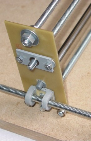
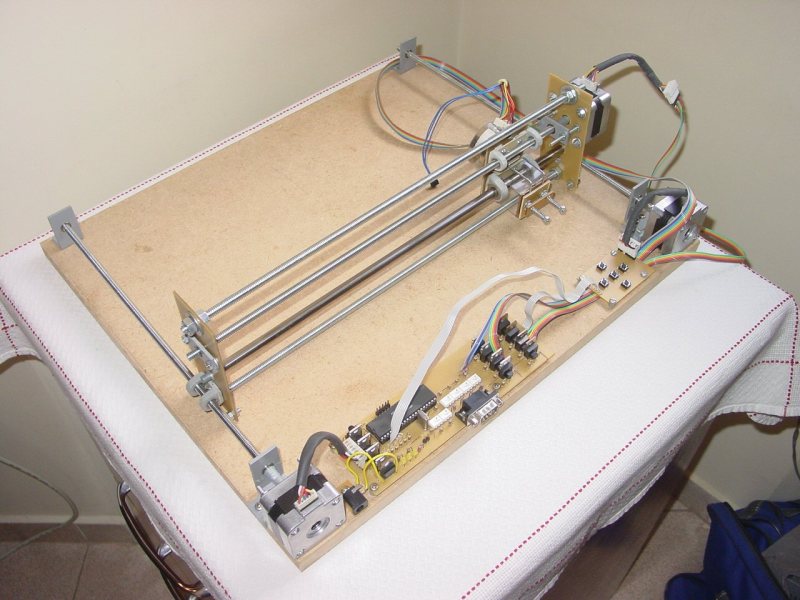
The design goal was to keep this machine as low-cost as possible while at the same time using materials that can be found around any tinkerer’s shop or at least purchased locally. First of all, you’ll notice that there is only one linear rail, yes, one rail for two axes of movement. The single rail was removed from an inkjet printer along with the mating bushing that originally allowed the print head to move freely back and forth. A threaded rod lead screw does double duty here, keeping the X axis carriage from rotating around the linear rail and also transmitting the force to move the carriage back and forth. Both the lead nut and bushings are held in place with cast-epoxy mounts.
 As unique as the X axis is, the Y sure gives it a run for its money. No linear rails are used, two lead screws are the only things that maintain the gantry’s position. To prevent gravity from pulling the gantry down and bending the Y axis lead screws, there are a couple of bearings on either side that ride along the bed of the machine. The frame material also hits the cheap target, it’s made from blank PCB board. A PIC16F877 microcontroller and a handful of mosfets control the motors. [msassa11] built this control circuit but admits it’s performance is not that great, it’s noisy and loses torque at high speed.
[msassa11] certainly proves that he is extremely resourceful with the outcome of this project. He met his goal of building an extremely inexpensive CNC machine. Check out his project page to see a ton of photos and find out what other unconventional ideas he used to build his machine.


And he also managed to not use any cap at all in his whole circuit.
You have good eye.
Wow you’re right. How does this thing even work without decoupling capacitors?
Who says it works? I only see still pictures, and NO examples of work actually done by this plotter. If I built this thing, and it worked, I would certainly be showing off something it made. Just speaking for myself, of course.
That’s because the videos are on a different page: http://myhobbyprojects.com/drupal-7.16/?q=plotter_videos
Nice project.
Regarding: “To prevent gravity from pulling the gantry down and bending the Y axis lead screws, there are a couple of bearings on either side that ride along the bed of the machine.”
This doesn´t prevent the gantry lo lift up from the bed due to tool pressure… I think that a rail above those bearings would help.
With such construction almost any tool pressure will bend everything. Even routing in wood would be too hard. BUT this is plotter it only draws lines, not cnc router. Also this whole machined is optimized for lowest cost sacrificing EVERYTHING. It is cheap and nothing else, but it is fit for it’s purpose, which is drawing on paper.
“He met his goal of building an extremely inexpensive CNC machine.”
Agreed. Note what is said and what is not said here. It’s cheap. It qualifies as a CNC machine. That’s it.
But I want to have a pointless argument about the meaning of words!!
It’s not meaningless. A “CNC router” has to resist forces involved in cutting material with a router. A “plotter” has only to resist the rolling friction of a pen.
I can show you lots and lots of bicycles that can’t carry heavy freight or operate on high-speed highways. This doesn’t mean they’re poorly-made bicycles.
The problem with the threaded steel rods is that they often come slightly bent. If you use one for both the guide rail and the propulsion, the whole thing will wobble up and down and side to side.
Dax is right, having built a CNC based on threaded rods, they are almost always bent. I had to bend mine to straighten them and they still aren’t perfect
Nothing like spending a saturday hour at the hardware store running your eye down all the threaded rod in the bin looking for the one thats not been corkscrewed by the threader.
Not to mention that when you run your fingers down the lenght of it, you can feel the thickness vary slightly. The threads themselves are non-linear because of it, since the nut catches at a different radius at different spots.
If it’s just a plotter and not a router, it’s probably not extremely fast. How many turns of the lead screw does it take to move the pen from one corner to another? But if it’s to be used with a relatively low powered laser for engraving on wood for example, it shouldn’t be a problem because the process is going to be slow anyway.
Nicely done. The lack of capacitors as pointed out previously by Indyaner is weird, but I guess they can be added across the crucial parts of the circuit as an afterthought.
I’m intrigued by “cast epoxy” parts. Just how the heck was THAT done?
Just like how any casting is done, only you use epoxy materials. http://lcamtuf.coredump.cx/gcnc/ch4/
The appearance of the parts of interest does not match that of the parts in the article you link, which uses expensive molding materials. What I was intrigued by was parts that are claimed to be of epoxy, made by somebody interested in CHEAP. Thank you.
But thank you for the link just the same – that looks like a pretty comprehensive guide to making stuff out of plastic.
It’s not hard
Oh man, I am in dire need of a cheap, cheap, CHEAP (seriously, I’m like, poor, AND stupidly trying to start a business with no money or credit) plotter that could cut designs in big pieces of Rubylith film right off the roll, probably with a bladeholder and blade for a CraftRobo. (To make silkscreen film positives.)
I’m sick of being restricted by the 7.78″ working width of my Silhouette SD. :(
I like it! I can think of a lot of uses for it too. I like that it can label cds. Also, it could make game tokens etc! Great job!