Cheap Unique CNC Plotter

DIY Plotter Strives For Cheapest CNC Machine Title

Arguably, taking the plunge into the CNC hobby does indeed have potential to end up costing more than expected. But that should be no reason to deter anyone from doing it! [msassa11] shows us how to do it in full effect with his definitely unique and extremely inexpensive homemade plotter.

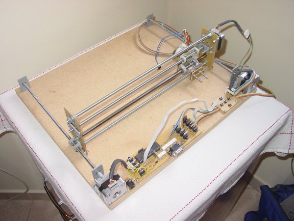
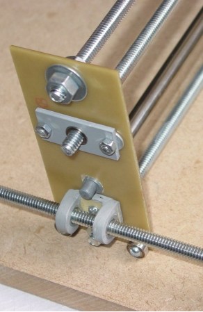
The design goal was to keep this machine as low-cost as possible while at the same time using materials that can be found around any tinkerer’s shop or at least purchased locally. First of all, you’ll notice that there is only one linear rail, yes, one rail for two axes of movement. The single rail was removed from an inkjet printer along with the mating bushing that originally allowed the print head to move freely back and forth. A threaded rod lead screw does double duty here, keeping the X axis carriage from rotating around the linear rail and also transmitting the force to move the carriage back and forth. Both the lead nut and bushings are held in place with cast-epoxy mounts.

uniquecnc-closeupAs unique as the X axis is, the Y sure gives it a run for its money. No linear rails are used, two lead screws are the only things that maintain the gantry’s position. To prevent gravity from pulling the gantry down and bending the Y axis lead screws, there are a couple of bearings on either side that ride along the bed of the machine. The frame material also hits the cheap target, it’s made from blank PCB board. A PIC16F877 microcontroller and a handful of mosfets control the motors. [msassa11] built this control circuit but admits it’s performance is not that great, it’s noisy and loses torque at high speed.

[msassa11] certainly proves that he is extremely resourceful with the outcome of this project. He met his goal of building an extremely inexpensive CNC machine. Check out his project page to see a ton of photos and find out what other unconventional ideas he used to build his machine.

ham radio

Fox Hunting With A Raspberry Pi

No, not a real fox! [KM4EFP] is a ham radio operator with a passion for fox hunting, which is an event where several radio operators attempt to find a broadcasting beacon (a “fox”) using radio direction finding techniques. [KM4EFP] has just built his own portable fox using a Raspberry Pi in a very well-built enclosure.

Since the fox could be outside for a while, the project was housed in a reasonably weatherproof ammunition case. A mount for an antenna was attached to the side, and it is hooked up to a GPIO pin on the Raspberry Pi. The entire device is powered by a 6000 mAh battery pack which allows the fox to broadcast long enough to be found.

The software running on the Raspberry Pi is very similar to the Pi FM transmitter program but it is specially made for ham radio broadcasting instead. Almost no extra hardware is needed to get the Pi broadcasting radio, as these software packages can drive the antenna directly from the GPIO pin. This is a great twist on the standard FM transmitter that ham radio enthusiasts everywhere can use to start finding those wily foxes!

Using Router SoCs As WiFi Modules (Yet Again)

8-bit AVRs and 32-bit ARMs do one thing, and one thing well: controlling other electronics and sensors while sipping power. The Internet of Things is upon us and with that comes the need for connecting to WiFi networks. Already, a lot of chips are using repackaged System on Chips to provide an easy way to connect to WiFi, and the USR-WIFI232-T is the latest of the bunch. It’s yet another UART to WiFi bridge, and as [2XOD], it’s pretty easy to connect to an AVR.

The module in question can be had through the usual channels for about $11, shipped straight from China, and the only purpose of this device is to provide a bridge between a serial port and a wireless network. They’re not that powerful, and are only meant for simple tasks,

[2XOD] got his hands on one of these modules and tested them out. They’re actually somewhat interesting, with all the configuration happening over a webpage served from the device. Of course the standard AT commands are available for setting everything up, just like the ESP8266.

With a month of testing, [2XOD] has found this to be a very reliable device, logging temperatures every minute for two weeks. There’s also a breakout board available to make connection easy, and depending on what project you’re building, these could be a reasonable stand-in for some other popular UART -> WiFi chips.

Nixies And Raspis For A Modern Vintage Calculator

There are a few very rare and very expensive calculators with Nixie tube displays scattered about calculator history, but so far we haven’t seen someone build a truly useful Nixie calculator from scratch. [Scott] did just that. It’s a complete, fully-functional electronic calculator with all the functions you would expect from a standard scientific calculator.

The calculator uses IN-12 Nixies, the standard for anyone wanting to build a clock or other numerical neon discharge display. Each Nixie is controlled by a K155D driver chip, with the driver chip controlled by an I2C IO expander.

The keypad is where this gets interesting; electronics are one thing, but electromechanicals and buttons are a completely new source of headaches. [Scott] ended up using Cherry MX Blue switches, one of the more common switches for mechanical keyboards. By using a standard keyboard switch [Scott] was able to get custom keycaps made for each of the buttons on his calculator.

The brains of the calculator is a Raspberry Pi, with the I2C pins going off to listen in on the several IO expanders on the device. A Raspi might be a little overkill, but an Internet-connected calculator does allow [Scott] to send calculations off to WolframAlpha, or even the copy of Mathematica included in every Pi.

[Scott] has put his project up on Kickstarter. Videos below.

Continue reading “Nixies And Raspis For A Modern Vintage Calculator”

How A Real 3D Display Works

There’s a new display technique that’s making the blog rounds, and like anything that seems like its torn from [George Lucas]’ cutting room floor, it’s getting a lot of attention. It’s a device that can display voxels in midair, forming low-resolution three-dimensional patterns without any screen, any fog machine, or any reflective medium. It’s really the closest thing to the projectors in a holodeck we’ve seen yet, leading a few people to ask how it’s done.

This isn’t the first time we’ve seen something like this. A few years ago. a similar 3D display technology was demonstrated that used a green laser to display tens of thousands of voxels in a display medium. The same company used this technology to draw white voxels in air, without a smoke machine or anything else for the laser beam to reflect off of. We couldn’t grasp how this worked at the time, but with a little bit of research we can find the relevant documentation.

A system like this was first published in 2006, built upon earlier work that only displayed pixels on a 2D plane. The device worked by taking an infrared Nd:YAG laser, and focusing the beam to an extremely small point. At that point, the atmosphere heats up enough to turn into plasma and turns into a bright, if temporary, point of light. With the laser pulsing several hundred times a second, a picture can be built up with these small plasma bursts.

2-fig2

Moving a ball of plasma around in 2D space is rather easy; all you need are a few mirrors. To get a third dimension to projected 3D images, a lens mounted on a linear rail moves back and forth changing the focal length of the optics setup. It’s an extremely impressive optical setup, but simple enough to get the jist of.

Having a device that projects images with balls of plasma leads to another question: how safe is this thing? There’s no mention of how powerful the laser used in this device is, but in every picture of this projector, people are wearing goggles. In the videos – one is available below – there is something that is obviously missing once you notice it: sound. This projector is creating tiny balls of expanding air hundreds of times per second. We don’t know what it sounds like – or if you can hear it at all – but a constant buzz would limit its application as an advertising medium.

As with any state-of-the-art project where we kinda know how it works, there’s a good chance someone with experience in optics could put something like this together. A normal green laser pointer in a water medium would be much safer than an IR YAG laser, but other than that the door is wide open for a replication of this project.

Thanks [Sean] for sending this in.

Continue reading “How A Real 3D Display Works”

Undershield, DIY Arduino Battery Shield

Battery Shield Mounts Underneath The Arduino

So, what do you do when your Arduino project needs to operate in a remote area or as a portable device? There are LiPo battery shields available, and although they may work well, recharging requires access to a USB port. You can also go the 9v battery route plugged into the on-board regulator of the Arduino but the low mAh rating of a 9v won’t allow your project to stay running for very long. [AI] needed a quick-change battery option for his Arduino project and came up with what he is calling the AA Undershield.

As the name implies, AA sized batteries are used in the project, two of them actually. Yes, two AA batteries at 1.5v each would equal only 3 volts when connected in series. The Arduino needs 5v so [AI] decided to use a MAX756 DC-to-DC step-up regulator to maintain a steady stream of 5v. This article has some nice graphs showing the difference in performance between a 9v battery being stepped down to 5v verses two AA’s being bumped up to 5v.

The ‘under’ in Undershield comes from this shield being mounted underneath the Arduino, unlike every other shield on the planet. Doing so allows use of a standard 0.100″-spaced prototype PCB and is an easy DIY solution to that odd-sized space between the Arduino’s Digital 7 and 8 pins. The Arduino mounts to the Undershield via its normal mounting holes with the help of some aluminum stand offs.

[AI] did a great job documenting his build with schematics and lots of photos so that anyone that is interested in making one for themselves can do so with extreme ease.

Very Large Touchpads For Very Old Computers

Way back when most of our demographic was in diapers, engineering workstations had huge touchscreens for plotting drawings in CAD programs, drawing, and just about everything a Wacom tablet does today. Finding one of these touch pads now is a fool’s errand, more so than finding the computer it was attached to, but [Daniel] figured out a way to relive those days of large touchpads and old computers with a resistive touchscreen and an MSX computer (portuguese, google translatrix).

[Daniel] is using a touchscreen normally used for a monitor, and with the right bit of code on a PIC16F micro, pressure on the touchscreen can be translated into X and Y coordinates. Using the PIC was a great choice in this instance: it’s possible to multiplex ports on an ADC pin with a PIC, making the entire system extremely efficient and easy to calibrate.

After that, it’s just a matter of plugging the output of the microcontroller into the touchpad connector of the MSX and writing a few lines of BASIC to draw a point on the screen. Video below.

Continue reading “Very Large Touchpads For Very Old Computers”