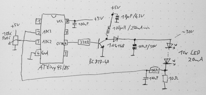
This schematic is all you need to build your own voltage converter. [Lutz] needed a converter that could boost 5 V to 30 V to power a string of LEDs. The solution was to use low cost ATtiny85 and some passive components to implement a boost converter.
This circuit follows the classic boost converter topology, using the ATtiny85 to control the switch. The 10 ohm resistor is fed back into the microcontroller’s ADC input, allowing it to sense the output voltage. By measuring the output voltage and adjusting the duty cycle accordingly, the circuit can regulate to a specified voltage setpoint.
A potentiometer is used to change the brightness of the LEDs. The software reads the potentiometer’s output voltage and adjusts the voltage output of the circuit accordingly. Higher voltages result in brighter LEDs.
Of course, there’s many other ways to implement a boost converter. Most practical designs will use a chip designed for this specific purpose. However, if you’re interested in rolling your own, the source and LTSpice simulation files are available.


Great way to reduce component count if LED brightness is to be controlled by a uC anyways. In every other case I would just throw in a dedicated LED driver and don’t worry about correct regulation.
I believe he is measuring the voltage across the 10 ohm resistor, being proportional to the current through it and the leds. So he is regulating the current and not the voltage, which makes some sense for a led driver…
It makes all the sense, because you can’t know from the voltage alone if you’re overdriving your LEDs.
All the sense
All teh senses are belong to the ATTiny! Resistance is futile!! :)
He implemented a feedback loop such as the one present in specialized chips like the well known mc34063 which can be used to regualte voltage or current when driven by a voltage dependent on current draw (ie. voltage across a resistor in series to the load). Since the feedback is a negative one he needs to read a voltage that rises when current rises, in order to get automatic current limiting.
“The 10 ohm resistor is fed back into the microcontroller’s ADC input, allowing it to sense the output voltage.”
Actually, it’s measuring the output *current*, by measuring voltage across a known resistance. Once both voltage and resistance are known, Ohm’s Law can be used to determine the current.
The “output voltage” would be not just the voltage across the resistor, but the LEDs too. And when driving LEDs it’s not very useful to know or directly control that, because a small change in voltage can cause a huge change in current. Even if you carefully initially set the voltage to something that results in a reasonable current, and keep the voltage there, the current will *still* change with changes in LED temperature. The hotter a LED gets, the more current it draws at a fixed voltage, which in turn makes the LED hotter, and so on – possibly progressing to full “thermal runaway” and LED failure. Finally, should any single LED in a series fail in a way that it behaves as a short, the increased voltages across remaining LEDs will typically destroy them in rapid succession.
Current control has none of these issues and is pretty much the norm for LED drivers.
Actually it’s measuring a scaled version of the voltage output from the voltage divider network. If he was measuring the current across the resistor, he would need an opamp to convert the differential measurement to single ended for the ADC.
There are no voltage dividers in the circuit. The ADC is measuring the voltage drop across the 10R resistor to workout the current, no differential stuff is needed here since the other end of the resistor is connected to ground.
Yeah he’s measuring the drop over the sense resistor for current, not voltage control. He doesn’t actually measure the voltage – so he probably will have issues under an open circuit condition.
Regulation is achieved through voltage feedback taken through the uC ADC. This introduces a delay (equal to the converter delay) in the loop which might affect the loop stability. I wonder how to analyse the stability of such a loop. Any ideas guys?
It’s not really a big deal for an LED because they’re not a very unstable load.
Even if they were, it wouldn’t affect anything, since an AVR takes only 13 cycles to read an ADC pin and, at its fastest, 256 cycles to overflow the PWM counter and generate a single pulse.
To be fair, a converter can very easily still be unstable all by itself even with a perfect stable, unchanging load. It all depends on the frequency roll-off and phase characteristics of the control loop.
However, in this case it’s only being updated at 1 kHz, and the PWM value is incremented or decremented each time only by 1 (rather than using some kind of proportional-with-added-poles-and-zeros controller) so I have a strong feeling this is one of those inherently stable control schemes, where the effective bandwidth and gain of the control loop are low enough that it’s never going to be an issue. I’ve never actually analyzed the loop dynamics of a non-analog-control power supply before though.
Nice simple control scheme which fits the application just fine without bringing in any extra sources of possible problems.
Unless your power supply has lower stability…. I thing for a LED it is safe to make the loop regulation not symmetrical: current too high drop the DC by a lot, current too low: increase DC by a bit. This should make it reasonable enough to run on the small micro.
It takes 13 cycles of the ADC clock, that cannot be higher than 200Khz, the max sample rate of the atmega/attiny ADC’s is in the 15Khz range, and that is the limit, no mather if you run the micro at 1Mhz or at 20Mhz.
You can run the ADC happily at a 1MHz clock and you’ll still get ~10 bits out of it. In fact, you can take it up to 4MHz and still get around 6 bits! It depends what your needs are.
Atmel recommends an ADC clock in the range of 50kHz to 200kHz to get the full 12 bits out of it – you may not need this much precision though.
You can scale the ADC clock to be the system clock divided by any power of two.
You can model the ADC delay by adding a RC low pass filter (LPF) in the feedback path. The RC low pass filter (1k, 0.1uF) already in the feedback path is going to dominate anyways. (i.e. its transient response sucks as a power supply) Thankfully, there isn’t much need for this as LED load is constant and likely running from a regulated 5V source, so nothing is going change quickly.
If the control loop is implemented as a PID controller, that LPF is the I term. You can improve the stability and the response by reducing the P and increasing the D term.
Add a Padé approximant for an e^{- tau s} term in the transfer function, and proceed as normal.
Can please someone tell me, what is the purpose of the RC circuit (1k and 100nF)? I mean, the 1k resistor would be reasonable to prevent a lot of current to flow into ADC of uC. But that resistor, I believe, forms a voltage divider with the 10R resistor and probably also a voltage divider with the internal ADC circuit (althought both dividers effects are nonsignificant because they are two orders of magnitude lower/higher in value). The point of that 100nF capacitor is a mystery to me, however. Thanks!
It’s a low-pass filter – it keeps high frequencies from feeding into the ADC (the corner frequency of the filter, the point at which it starts to cut out more and more of the signal, is about 1.6 kHz). There are two reasons for this:
One is that in a switching power supply the noise generated by the sharp switching transitions couples into EVERYTHING and can cause all kinds of problems if you don’t filter it out of the control signals.
The other reason is because of the Nyquist rate – if the input signal to an ADC has components at a higher frequency than half the ADC’s sampling rate (for example, the ADC samples 100 times per second but there’s an 80 Hz component in its input signal), it’ll show up in the ADC’s output at a lower frequency. Basically, if you’re trying to measure an almost-DC value and you don’t filter out frequencies above half your sampling rate, your measurements will have additional errors introduced by those higher frequencies. How much this matters depends on the application, and sometimes for low-accuracy kinds of things without any comparatively-high frequencies kicking around in the circuit, you can get away without this – however, a switching supply is one place you’re guaranteed to have above-half-sampling-rate frequencies everywhere.
The ADC input is high-impedance, there is almost no current flowing in or out of it so there no dividers there. The RC circuit 1k + 100n is to help reduce noise and smooth out the signal from all the transistor switching stuff.
(Tried adding a comment before but it’s not showing up as pending like my others so I’m not sure if it went through – apologies if this is a duplicate)
The RC circuit here is working as a low-pass filter, with a corner frequency of about 1.6 kHz. Signals below the corner frequency are passed (mostly) unchanged, while anything above its corner frequency is attenuated more and more as the frequency increases. There are two reasons why it’s filtering the current sense signal:
One is that in a switching power supply, noise from the fast-changing switch transitions couples EVERYWHERE, and can cause all kinds of problems if it gets into the analog control signals.
The other is because of the Nyquist rate – if you sample a signal with an ADC, and it has frequency components that are more than half the sampling rate (for example, you’re sampling 100 times per second and there’s an 80 Hz component to the input signal), that component will show up at a lower frequency in the ADC’s sampled output. Basically, if you’re trying to measure an almost-DC value, frequencies above half the sampling rate will introduce additional errors to your measurement. Sometimes with low-accuracy things where there aren’t any comparatively-high-frequency parasitics kicking around in the circuit (like doing a typical “read pot value from microcontroller” sort of thing) you can get away with not filtering. However, a switching power supply is one place you’re guaranteed to have all kinds of frequency components way above this circuit’s 1 kHz sampling rate.
loop stability
The high voltage is generated from pulses of current at the boost converter. This is smoothed somewhat by the 100uF cap, but there will still be some ripple on the synthesized supply. Also, noise from the environment or the pulsing circuit will introduce voltages.
The voltage across the resistor will then also be “pulsed”, and not a steady indication. The ADC has an extremely high impedance, so it will faithfully read these pulses and noise, giving an erroneous reading.
The cap and resistor act as an integrator – it smooths out high frequency pulses, and presents only the DC voltage to the ADC.
Noise and high frequency pulses see the capacitor as a dead short, so the noise sees a 1K resistor to ground. The ADC has an extremely high input impedance on the order of 100 mOhm, so the amount of signal presented to the ADC is 1K/(100m+1K) , the standard resistor divider. Virtually none of the noise signal gets through the ADC.
DC and slowly changing signals see the cap as an open circuit, which is infinite resistance. The amount of signal presented to the ADC is inf/(100m+inf) which is very close to a factor of 1, so all of the DC signal gets through the ADC.
The 1K resistor is used to slow down the response of the integrator. Without it, extremely slowly changing voltages (on the order of seconds) would be integrated, and the system would not be able to respond quickly to changes.
The 100uF and 1K multiply together for a time constant of 0.1 second. Voltage changes slower than this will get through, while faster pulses will get integrated.
Fantastic response! Thanks.
The RC network is not a divider as Zak mentioned. It is there to help prevent system oscillations by reducing the system ‘Q Factor’. It is effectively a ‘Low Pass’ filter to block higher frequencies that the system may oscillate at by introducing a time delay in the feedback circuit.
http://en.wikipedia.org/wiki/RC_time_constant
http://en.wikipedia.org/wiki/Low-pass_filter
http://en.wikipedia.org/wiki/Q_factor
Thanks for all the answers, you guys are great!
A very nice minimum component count solution with the ability to program the output (twinkles, stribe etc).
If you did not care so much for the added features though an alternative solution would be to remove the microprocessor altogether and use a secondary reversed winding on the inductor in the transistor base circuit similar to the joule thief. I’ve used that type of circuit in the past to power 10+ LED’s in series. By controlling the component values it is possible to get a safe stable output with the advantage that it can be run from any single cell of >0.75v
uC source code?
Here a circuit using a PIC10F200 to boost current to drive a white LED . The feedback loop is digital and the firmware code is only 13 assembly instructions. It works very well although it is not design to control LED intensity. Schematic show only 1 LED but more could be put in series.
http://picatout-jd.blogspot.ca/2013/11/led-blanche-sur-3-volt.html
Something also has occured to me in that the circuit as shown does have a catastrophic failure mode should the LED’s ever be disconnected while it is on.
Because there is only current feedback to the uC and no monitoring of the collector emitter (C-E) voltage on the transistor then unless there is some programming magic a disconnection of the load will result in the C-E voltage will potentially rise until it reaches the transistors breakdown voltage, drastically shortening the life of the transistor.
Adding a simple voltage divider across the transistor with its output passed via a low pass filter to a pin on the uC would allow it to detect such overvoltage events and shut off the output.
Alternatively you could strap a zenner and resistor in series across the transistor as a crowbar snubber.
I am assuming you mean the reverse breakdown voltage. Is that what you are saying?
The “Magic” wouldn’t be very difficult. Zero current for all PWM’s suggests a fault – shut down the PWM. A reset (power cycle) would be needed to resume operation… but it would also make you look at the device.
I would add 3 more things to make this safer:
1. a zenner diode across the leds protects in case the circuit is open, for safety or in case you use the circuit with disconnected led’s.
2. a resistor in the transistor’s emitter can be used to measure the current, just feed the voltage back to the internal comparator and use the internal 1V reference. In normal operation you should not drop more than 25…50mV on the resistor, but then you can detect too much current consumption (2…4 times normal).
3. watchdog should be there and cleared periodically, you don’t want to leave the transistor on all the time by accident.
You could also drop the 100uF cap since it does not matter if the LEDs are on for a smaller than 100% duty cycle, the operating frequency is large enough for them to appear constantly on.
This seem over engineering for such a simple application.
If something bad append Q1 burn and can be replaced cheaply.
Until your house burns down because your circuit had no way to limit the current….
That should teach you not to use the 1kA power supply.
I thought the definition of a trasnsistor was that it was a device placed in a circuit to protect the fuse }:¬)
Good one. Never heard that before. Your comment was about the only one I understood on this entire thread. Everything sounds vaguely familiar from college 20 years ago and following HAD, but I feel really stupid right now.
#1-3 sound reasonable (it’s possible they’re over-engineering, but either way they are definitely things that would make it safer), but leaving out the 100uF cap seems to me like a bad idea. If this was a buck converter, having no output capacitor can be ok for LEDs because it has a continuous output current held by the inductor anyways (the capacitor just decreases ripple), but with a boost converter my intuition says it just wouldn’t operate properly cycle-to-cycle – sure, you’d still get the boost effect and it would produce higher-output-voltage pulses but I think it wouldn’t regulate very well and it would be hard to predict exactly how much voltage would be across the LEDs or how much current it would be putting through them for any given settings (as in, much more sensitive to everything and easier to blow things up). Also not sure how much the LEDs would like having the short but much-higher-peak-power pulses necessary to keep the average power the same. Measuring the average current through the LEDs with the current sense also wouldn’t be the same, as you’d have lots of short high-amplitude pulses which you’d have to filter – would have to increase the current sense filtering by a whole lot and put a scope on it to verify it’s actually doing what you want. It’s possible I’m wrong (I’ve designed and debugged a decent number of switching power supplies but I’m still definitely no expert!) and running a boost converter without any output cap would work ok, but it seems like a whole lot of trouble and risk (especially making sure that it’s actually working properly in every way and won’t fry itself in a week) for a small benefit that’s not really worth it.
The mostly likely scenario is that the LED chain is external to the circuit and if there is intermittent open connections. So cap get charged to a high voltage while it is opened and zaps the lot of them when connection is made again. A zener diode at a slightly higher voltage is connected to the circuit in parallel with the LED can prevent this from happening. When the chain is disconnected, the zener closes the feedback loop and essentially maintaining the output voltage to a safe level (for the cap, diode, transistor and the LED).
You can also monitor the voltage to prevent this or use a smart control loop that notice the current has dropped to zero even the pwm duty has been increased.
How do you detect when the circuit is back up, or do you just shut it down to failure mode and wait for a power cycle?
For failure recovery you can either latch the fault condition until a power cycle or do a time out/retry unlimited times (hick-up) or even a combination of the two (limited retry cycles). Once the current is detected during a retry running the PWM at low duty cycles, then resume the proper brightness.
For the Zener diode case, if the LED connection is back, the LED would conduct because it has a lower drop than the Zener.
The problem is, if you do a timeout-retry and someone is touching the wires trying to troubleshoot why it isn’t working, they get a nasty shock because the voltage can rise quite high over repeated re-attempts.
That’s why I prefer the Zener diode solution myself as it is a simple, cheap and reliable hardware solution without actually going to all the firmware debugging and verification. There are always those who can’t stand extra hardware.
As for the retry, I specified a low duty cycle PWM to keep the voltage low. LED conducts small amount of current at much lower voltages even well before you hit near 3V per LED when they give up appreciable of light. You just need a tiny bit that shows up in the ADC above noise. If you only ramp up just enough voltage to do a detection. Once that is detected, then you can let the feedback loop ramp up the current.
I like #1-3. Plus a good old-fashioned fuse.
But dropping the 100uF cap, in general, wouldn’t be a good idea. It would result in the LEDs being driven with large pulses of current.
Let’s say you have a LED rated for 20mA. Drive it at 20mA, constant current, and you get 100% light output.
What if you drive it at 40mA, 10Khz PWM with 50% duty cycle instead? This results in the same current, averaged over time. And essentially the same LED heating. But LEDs are non-linear – the more current you push through one, the less efficient the conversion of power to light. So for the time the LED is on, with 40mA going through it, you’ll get around 150% light output, rather than the 200% one might expect. Average that with the off time and you’re only getting 75% average light output – less than if it were being driven constant current.
This only gets worse as the peak current goes up. I’ve heard of folks pushing very brief 0.5A pulses through 20mA LEDs, For this 25X increase in power, you get only 4-5X output in light. This may be useful when using a common LED for rangefinding or communications, but terrible for illumination.
And if you’re using white LEDs for illumination, there’s an additional issue. White LEDs are typically royal blue, with a mix of phosphors coating it. These phosphors convert a portion of the output to a variety of colors, approximating white. But phosphor is also non-linear, and can be saturated with light to the point where it becomes an absorber more than a converter. LED manufacturers only add enough phosphor to deal with the expected light output. Pulse overdrive a white LED, and you get even worse efficiency due to losses in the phosphor. Plus spectral shift due to a higher proportion of the native royal blue coming through unconverted, making it no longer look very white.
To relate this to a personal hobby, if building a DIY LED aquarium light fixture, it’s common practice to deliberately underdrive LEDs at only 50-75% of their rated current. This results in higher efficiency and longer lifetime, at the expense of using more LEDs to reach an illumination target; but long-term the practice can pay for itself many times over during the lifetime of the fixture. (Not so with many commercial fixtures, as the initial expense of more LEDs and supporting components would mean a higher price and less sales. LEDs are typically driven at 90-100% in fixtures from reputable manufacturers. Or overdriven in cheap imports, I’ve seen one running at 150%. Needless to say I strongly favor DIY when it comes to my aquarium lights.)
And just for amusement, an extreme example. I recall reading an article about some researchers pushing (IIRC) a few pA through an IR LED, and finding it had *over* 100% efficiency. It actually got slightly colder, converting ambient heat to current; a real-world example of Maxwell’s Demon.
For a switching power supply, check out the PIC16F17xx series.
Instead of using and ADC to read a feedback current it would be faster to use an inbuilt comparator and use the processor’s interrupt to handle it. The reference voltage for the comparator can sometimes be the built-in bandgap reference in the processor itself, or a part like the TL1431B.
You lose a lot of efficiency when you have a large current sense resistor in higher current switching designs. The smaller the resistor value, the smaller the feedback signal you have to deal with. To compensate for this a PGA can be used, some processors have one built in.
Compare the NCP3065 to the MC33063 and a big difference is the feedback voltage.
Those series of PIC’s also have built in OP Amps which you could use to amplify the voltage drop across the lower value current sense resistor.
One major problem when the load disconnected since is current controlled the output voltage will try to increase to infinity and will burn output transistor and avr adc input.So tracking output overvoltage using one more ADC input and a resistor divider network is the most needed.Also an RC 10nf/1K snubber connected between collector and ground is useful.I put few times something similar inside led tv as a replacement to the original.