It’s Switch Mode, But Not As You Know It

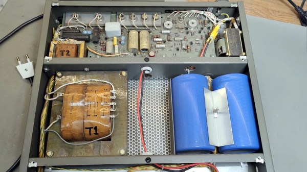
The switch-mode power supply has displaced traditional supplies almost completely over the last few decades, being smaller, lighter, and more efficient. But that’s not to say that it’s a new idea, and on the way to today’s high-frequency devices there have been quite a few steps. An earlier one is the subject of a teardown video from [Thomas Scherrer OZ2CPU], as he takes a look at a 1960s HP power supply with a slightly different approach to regulation for the day. Instead of a linear regulator on its conventional transformer and rectifier circuit, it has a pair of SCRs in the mains supply that chop at mains frequency. It’s a switch mode supply, but not quite as you’re used to.

In fact, these circuits using an SCR or a triac weren’t quite as uncommon as you might expect, and could at one point be found in almost every domestic TV set or light dimmer. Sometimes referred to as “chopper” supplies, they represented a relatively cheap way to derive a regulated DC voltage from an AC mains source in the days before anyone cared too much about RF emissions, and though few were as high quality as the HP shown in the video below, they were pretty reliable.

If older switchers interest you, this is not the first one we’ve shown you from that era.

Continue reading “It’s Switch Mode, But Not As You Know It”

Minimizing Stress On A Coin Cell Battery

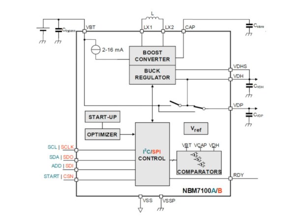
When it comes to powering tiny devices for a long time, coin cell batteries are the battery of choice for things like keyfobs, watches, and even some IoT devices. They’re inexpensive and compact and a great choice for very small electricity needs. Their major downside is that they have a relatively high internal resistance, meaning they can’t supply a lot of current for very long without decreasing the lifespan of the battery. This new integrated circuit uses a special DC-DC converter to get over that hurdle and extend the life of a coin cell significantly.

A typical DC-DC converter uses a rapidly switching transistor to regulate the energy flow through an inductor and capacitor, effectively stepping up or stepping down the voltage. Rather than relying on a single converter, this circuit uses a two-stage system. The first is a boost converter to step the voltage from the coin cell up to as much as 11 volts to charge a storage capacitor. The second is a buck converter which steps that voltage down when there is a high current demand. This causes less overall voltage drop on the battery meaning less stress for it and a longer operating life in the device.

There are a few other features of this circuit as well, including an optimizer which watches the behavior of the circuit and learns about the power demands being placed on it. That way, the storage capacitor is only charged up to its maximum capacity if the optimizer determines that much charge is needed. With all of these features a coin cell could last around seven times as long as one using more traditional circuitry. If you really need to get every last bit of energy from a battery, though, you can always use a joule thief.

Tracking Down Radio Frequency Noise Source, With Help From Mother Nature

Amateur radio operators and shortwave listeners have a common enemy: QRM, which is ham-speak for radio frequency interference caused by man-made sources. Indiscriminate, often broadband in nature, and annoying as hell, QRM spews forth from all kinds of sources, and can be difficult to locate and fix.

But [Emilio Ruiz], an operator from Mexico, got a little help from Mother Nature recently in his quest to lower his noise floor. Having suffered from a really annoying blast of RFI across wide swaths of the radio spectrum for months, a summer thunderstorm delivered a blessing in disguise: a power outage. Hooking his rig up to a battery — all good operators are ready to switch to battery power at a moment’s notice — he was greeted by blessed relief from all that noise. Whatever had caused the problem was obviously now offline.

Rather than waste the quiet time on searching down the culprit, [Emilio] worked the bands until the power returned, and with it the noise. He killed the main breaker in the house and found that the noise abated, leading him on a search of the premises with a portable shortwave receiver. The culprit? Unsurprisingly, it was a cheap laptop power supply. [Emilio] found that the switch-mode brick was spewing RFI over a 200-meter radius; a dissection revealed that the “ferrite beads” intended to suppress RFI emissions were in fact just molded plastic fakes, and that the cord they supposedly protected was completely unshielded.

We applaud [Emilio]’s sleuthing for the inspiration it gives to hunt down our own noise-floor raising sources. It kind of reminds us of a similar effort by [Josh (KI6NAZ)] a while back.

In-Depth Design Of A Flyback Converter

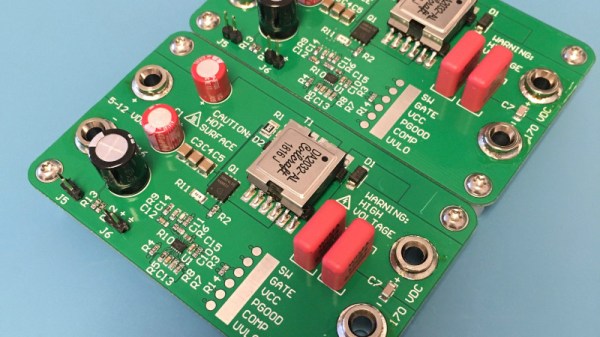
It is tempting to think of analogue and digital domains as entirely distinct, never to touch each other except like a cold war Checkpoint Charlie, through the medium of an ADC or DAC. In reality there are plenty of analogue effects upon digital circuitry which designers must be aware of, but there is one field in which the analogue and the digital are intricately  meshed. Switch mode power supplies use digital techniques to exploit the analogue properties of components such as inductors and capacitors, and can be astoundingly clever in the way they do this to extract the last fraction of a percent efficiency from their conversion. Thus their design can be something of a Dark Art, so it’s always interesting to have a good read explaining some of the intricacies. [James Wilson] has built a flyback step-up converter to power Nixie tubes, and his write-up follows the whole process in great depth.

This type of converter seems at first glance to be a simple step-up design with a transformer that has a primary and secondary, where in fact it relies on the collapse in magnetic field during the off period of its duty cycle to provide a spike in voltage and thus a step-up beyond that you’d expect from the transformer alone. The write-up takes us through all this starting from a theoretical perspective, and then goes further into the realm of component selection and the effects of component properties on the waveforms involved. If you have ever battled ringing in a switch mode power supply you may recognise some of this.

If this field interests you, then there is probably no better place to send you for a start than Jim Williams’ 1987 app note 25 for Linear Technology: “Switching Regulators for Poets“.

Switching Over To SMPS For Efficiency

[Hesam Moshiri] has built a variable switch-mode power supply over on hackaday.io. When prototyping a new circuit, often the goal is to get a proof-of-concept working as soon as possible to iron out all of the bugs it might have. The power supply can easily be an afterthought, and for smaller projects we might just reach for an adjustable LM317 voltage regulator to dial in the correct voltage and then move on with the meat of the project. These linear regulators are incredibly inefficient though, so if you find yourself prototyping with one of these often enough, it might be worthwhile to switch to something better.

While it’s easy to simply buy a switch-mode power supply (SMPS) that has everything you need, and rated for 90% or higher efficiency at the same time, getting one with an adjustable output isn’t as easy. This one is based on the relatively popular LM2576-Adj chip which handles the switching frequency part of the circuit automatically. You will also need some large capacitors, an inductor (one of the disadvantages of an SMPS circuit) and a small potentiometer to use as the feedback control for the LM2576. This special pin allows the output voltage of the SMPS to be precisely controlled.

Granted, this project might not be breaking any new grounds, but if you’ve never given serious thought to your small breadboard circuit power supplies, it’s definitely worth looking into. An improvement from a linear regulator’s 30% efficiency to 90% efficiency from an SMPS will not only save you a ton of energy but also solve a lot of heat dissipation problems. If you don’t want to build a switch-mode supply 100% from scratch, though, it might also be possible to modify an existing one to suit your needs as well.

Mains Power Supply For ATtiny Project Is Probably A Bad Idea

When designing a mains power supply for a small load DC circuit, there are plenty of considerations. Small size, efficiency, and cost of materials all spring to mind. Potential lethality seems like it would be a bad thing to design in, but that didn’t stop [Great Scott!] from exploring capacitive drop power supplies. You know, for science.

The backstory here is that [Great Scott!] is working on a super-secret ATtiny project that needs to be powered off mains. Switching power supplies are practically de rigueur for such applications, but compared to the intended microcontroller circuit they are actually quite large, and they’ve just been so done before. So in order to learn a thing or two, [Scott!] designed a capacitive dropper supply, where the reactance of the cap acts like a dropping resistor to limit the current. His first try was just a capacitor in series with an LED; this didn’t end well for the LED.

To understand why, he reverse-engineered a few low-current mains devices and found that practical capacitive droppers need a few more components, chiefly a series resistance to prevent inrush current from getting out of hand, but also a bridge rectifier and a zener to clamp things down. Wiring up all that resulted in a working capacitive dropper supply, but a the cost of as much real estate as a small switcher, and with the extra bonus of being potentially lethal if the power supply is plugged in the wrong way. Side note: we thought German line cords were polarized to prevent this, but apparently not? (Ed Note: Nope!)

As always, even when [Great Scott!]’s projects don’t exactly work out, like a suboptimal 3D-printed BLDC or why not to bother building your own DC-AC inverter, we enjoy the learning that results.

Continue reading “Mains Power Supply For ATtiny Project Is Probably A Bad Idea”

Bench Power Supply Uses Server Voltage Regulator

If you stuff a computer into a rack with a bunch of other machines, you’d better make it a tough machine. Server-grade means something, so using server parts in a project, like this high-wattage power supply using server voltage regulators, can take it to the next level of robustness.

But before [Andy Brown] could build this power supply, he had to reverse-engineer the modules. Based on what he learned, and armed with a data sheet for the modules, he designed a controller to take advantage of all the capabilities of them and ended up with a full-featured power supply. The modules are rated for 66 watts total dissipation at 3.3 volts and have a secondary 5-volt output. Using an ATmega328, [Andy] was able to control the module, provide a display for voltage and current, temperature sensing and fan control, and even a UART to allow data logging to a serial port. His design features mainly through-hole components to make the build accessible to everyone. A suitable case is yet to come, and we’re looking forward to seeing the finished product.

Can’t scrape together some of these modules on eBay? Or perhaps you prefer linear power supplies to switched- mode? No worries – here’s a super stable unregulated supply for you.

Continue reading “Bench Power Supply Uses Server Voltage Regulator”