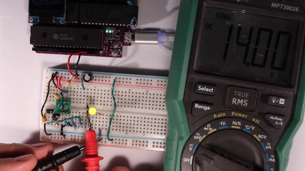
A purple PCB with an OLED display and various chips

A Neat Little Tool To Reset The Fuses On Your ATtiny

If you’re an experienced hacker, you’ve probably run into a problem at some point and thought “let’s make a tool to automate that”. A few hours later you’ve got your tool, but then realize that the amount of work you put into making the tool vastly exceeds what you would have needed to solve the original problem manually. That really doesn’t matter though: developing a fancy tool can be a rewarding experience that teaches you way more about the original problem than you would have learned otherwise. [sjm4306]’s ATtiny High Voltage Fuse Reset-er is a clever device that firmly falls into this category.

The problem it solves is familiar to anyone who’s ever worked with Atmel/Microchip’s ATtiny series of microcontrollers: set one of the configuration fuses incorrectly and you’re no longer able to reprogram your chip. Getting the ATtiny back to its original configuration requires a high-voltage programming step that involves pulling the reset pin to 12 V in what’s otherwise a 5 V system. You could simply grab a spare 12 V supply and hack together a level shifter with a few transistors, but where’s the fun in that?

[sjm4306]’s solution is built on a pretty purple PCB that contains an ATmega328, an OLED display, and sockets to accommodate various versions of the ATtiny series microcontrollers. To generate the required 12 V, one could simply use an off-the-shelf boost converter IC. But instead, he decided it would be interesting to make such a circuit out of discrete components and control it using the ATmega. After all, this chip already contains timers to generate PWM signals and an ADC to measure the converter’s output voltage, so all it took was to write some control logic in the form of a PID controller.

The end result, as you can see in the video embedded below, is a convenient little PCB that runs off a 5 V USB power supply and resets the fuses on your ATtiny at the push of a button. Sometimes, simple tools that do one thing well are all you need; however, if you’re looking for an all-in-one AVR programmer that also supports HV programming, check out this AVR Multi-Tool.

Continue reading “A Neat Little Tool To Reset The Fuses On Your ATtiny”

SuperCapacitors Vs Batteries Again

Supercapacitors are definitely not the same as batteries, we all know that. They tend to have a very low operating voltage, and due to their operating principle of storing charge on parallel plates, their discharge curve is quite unfriendly for modern microcontroller devices. Energy storage efficiency per unit volume is also low compared with modern lithium polymer (LiPo) batteries so all in all they don’t look all that useful for many of our projects. However, as [Andreas Spiess’] latest video demonstrates, they do have some redeeming features that might make them useful for certain embedded applications.

The low operating voltage initially looks like an issue for devices operating at a typical 3.3V, and it’s tempting to simply wire a few in series and roll with it. But as [Andreas] explains in his typically clear manner, it would be necessary to have a complex power stage, operating in buck mode with capacitor voltage above the required level, and in boost mode when it heads below. Too complex – it’s much easier to simply stick with a low voltage bank of paralleled supercaps, and just operate always in boost mode. Even doing this, you’re not realistically going to get more than a handful of hours operating voltage with an always active device.

So why bother at all with supercaps, surely using a LiPo is so much easier and better? In many cases the answer is definitely a yes. But LiPo cells must not be charged in freezing temperatures (apart from certain special low temp products), else the cell can rapidly be destroyed due to lithium metal deposition at the anode. Also you need to be careful charging them, especially when they’re heavily discharged, as they are easily damaged without the proper treatment. LiPo cells operate based on chemical principles – lithium ions literally have to move around inside the structure, and eventually the battery will wear out.

Supercapacitors have the advantage of very long life (but sometimes, they do leak) much more aggressive charging and discharging behaviours and will operate down to very low temperatures. This makes them very useful when a large amount of power is available sporadically (for super fast charge cycles) or in places where temperatures stay persistently very low, such as up a mountain were solar will work, albeit slowly, but LiPo batteries will definitely not be suitable.

Other battery chemistries are available, such as Lithium Iron Phosphate which can tolerate the cold. Also you can always just insulate the battery with an integrated heater and preheat the battery to a safe charging temperature as well. So, just like everything with electronics, it’s important to choose the correct parts for your application, and it all starts with the power source. Supercapacitors might just hit an appropriate price/performance point for that special application you had in mind.

Supercapacitors aren’t really suitable for many applications, like powering an eBike or running your laptop, but hey, they did it anyway.

Continue reading “SuperCapacitors Vs Batteries Again”

A scrolling name badge that uses LED matrices.

Scrolling Name Badge Is Sure To Break The Ice

Most makerspaces and hackerspaces have one night per week or month where the ‘space is open to the public in order to entice new people into joining up. Whereas most members just write their name in Sharpie on a piece of masking tape, [Madison] wanted to do something extra. And what better way to get people interested in your ‘space than by wearing something useful that came out of it?

The badge runs on an ATtiny45 and uses three 8×8 ultra-bright LED matrices for scrolling [Madison]’s name. It’s powered by a tiny LiPo battery that is boosted to 5 V. This build really shows off a number of skills, especially design. We love the look of this badge, from the pink silkscreen to the the typography. One of the hardest things about design is finding fonts that work well together, and we think [Madison] chose wisely. Be sure to check it out in action after the break.

Custom name badges are a great way to start conversations no matter where you go. Here’s one that uses EL wire and LEDs that light up in sequence for an animated effect.

Continue reading “Scrolling Name Badge Is Sure To Break The Ice”

Quick And (Not Very) Dirty Negative Voltage Supply

There comes a time in every hardware hacker’s career during which they first realize they need a negative voltage rail in their project. There also comes a time, usually ~10ms after realizing this, when they reach for the Art of Electronics to try and figure out how the heck to actually introduce subzero voltages into their design. As it turns out, there are a ton of ways to get the job done, from expensive power supplies to fancy regulators you can design, but if you’re lazy (like I am) you might just want a simple, nearly drop-in solution.

[Filip Piorski] has got you covered there. In a recent video, he demonstrates how to turn a “China Special” $1 buck converter from Ebay into a boost-buck converter, capable of acting as a negative voltage supply. He realized that by swapping around the inputs and outputs of the regulator you can essentially invert the potential produced. There are a few caveats, of course, including high start-up current and limited max. voltages, but he manages to circumvent some of them with a little clever rewiring and a bit of bodge work.

Of course, if you have strict power supply requirements you probably want to shell out the cash for a professionally-built one, or design one yourself that meets your exact needs. For the majority of us, a quick and easy solution like this will get the job done and allow us to focus on other aspects of the design without having to spend too much time worrying about the power supply. Of course, if power electronics design is your thing, we’ve got you covered there, too.

Continue reading “Quick And (Not Very) Dirty Negative Voltage Supply”

Investigating A Defective USB Power Bank Module

Call us old fashioned, but we feel like when you buy a piece of hardware, the thing should actually function. Now don’t get us wrong, like most of you, we’re willing to put up with the occasional dud so long as the price is right. But when something you just bought is so screwed up internally that there’s no chance it ever could have ever worked in the first place, that’s a very different story.

Unfortunately, that’s exactly what [Majenko] discovered when he tried out one of the USB-C power bank modules he recently ordered. The seemed to charge the battery well enough, but when he plugged a device into the USB output, he got nothing. We don’t mean just a low voltage either, probing with his meter, he became increasingly convinced that the 5 V pin on the module’s IP5306 chip literally wasn’t connected to anything.

So close, yet so far away.

Curious to know what had gone wrong, he removed all the components from the board and started sanding off the solder mask. With the copper exposed, his suspicions were confirmed. While they did route a trace from the chip to the via that would take the 5 V output the other side of the board, it wasn’t actually connected.

This is a pretty blatant bug to get left in the board, but to be fair, something similar has happened at least once or twice to pretty much everyone who’s ever designed their own PCB. Then again, those people didn’t leave said flaw in a commercially released module…

Continue reading “Investigating A Defective USB Power Bank Module”

The Bright Side Of The Moon Lamp: It’s Any Colour You Like

One of the easiest ways to get into hardware hacking is by piecing together a few modules and shoehorning them into a really cool home. For example, why buy a commercial moon lamp when you can spend 30+ hours printing your own, and a few more hours hacking the guts together?

[Amit_Jain] was inspired by a project that combined a color map and bump map of the moon into a highly-detailed printable model. Displeased with the lack of features like portability and pretty colors, [Amit] took it to the next level by designing a threaded cap that unscrews to show the streamlined guts of an off-the-shelf RGB LED controller.

[Amit] freed the controller board from its plastic box and soldered the LED strip’s wires directly to it. For power, [Amit] taped the board to the battery from an old cell phone and stepped it up to 12 V with a boost converter. We think this looks quite nice and professional, especially with the stand. A brief demo is on the rise after the break.

If you’ve got the room for a much, much larger light-up moon, you should go for it.

Continue reading “The Bright Side Of The Moon Lamp: It’s Any Colour You Like”

AVR Microcontroller Doubles Up As A Switching Regulator

[SM6VFZ] designed, built and tested a switched-mode DC-DC boost regulator using the core independent peripherals (CIP) of an ATtiny214 micro-controller as a proof of concept, and it looks pretty promising!

A Buck, Boost, or Buck-Boost switching regulator topology usually consists of a diode, a switching element (MOSFET) and an energy storage device (inductor/capacitor) in the power path, and a controller that can measure the output voltage, control the switching element and add safety features such as current limiting and temperature shutdown. A search for switching regulators or controllers throws up thousands of parts, and it’s possible to select one specifically well suited for any desired application. Even so, the ability to use the micro-controller itself as the regulator can have several use cases. Such an implementation allows for a software configurable switch-mode regulator and easy topology changes (boost, buck, fly back etc.).

The “Getting Started with Core Independent Peripherals on AVR®” application note is a good place to get an overview of how the CIP functionality works. Configurable Custom Logic (CCL) is among one of the powerful CIP peripherals. Think of CCL as a rudimentary CPLD — a programmable logic peripheral, which can be connected to a wide range of internal and external inputs such as device pins, events, or other internal peripherals. The CCL can serve as “glue logic” between the device peripherals and external devices. The CCL peripheral offers two LookUp Tables (LUT). Each LUT consists of three inputs, a truth table, a synchronizer, a filter, and an edge detector. Each LUT can generate an output as a user programmable logic expression with three inputs and any device that have CCL peripherals will have a minimum of two LUTs available.

This napkinCAD sketch shows how [SM6VFZ] implemented the boost regulator in the ATtiny214. The AND gate is formed using one of the CCL LUT’s. The first “timer 1” on the left, connected to one input of the AND gate, is free running and set at 33 kHz. The analog comparator compares the boosted output voltage against an internally generated reference voltage derived from the DAC. The output of the comparator then “gates” timer 1 signal to trigger the second “timer 2” — which is a mono-shot timer set to max out at 15 us. This makes sure there is enough time left for the inductor to completely release its energy before the next cycle starts. You can check out the code that [SM6VFZ] used to built this prototype, and his generous amounts of commenting makes it easy to figure out how it works.

Based on this design, the prototype that he built delivers 12 V at about 200 mA with an 85% efficiency, which compares pretty well against regular switching regulators. Keep in mind that this is more of a proof-of-concept (that actually works), and there is a lot of scope for improvement in terms of noise, efficiency and other parameters, so everyone’s comments are welcome.

In an earlier blog post, we looked at how ATmegas with Programmable Logic came about with this feature that is usually found in PIC micro-controllers, thanks to Microchip’s acquisition of Atmel a few years back. But we haven’t seen any practical example of the CCL peripheral in an Atmel chip up until now.