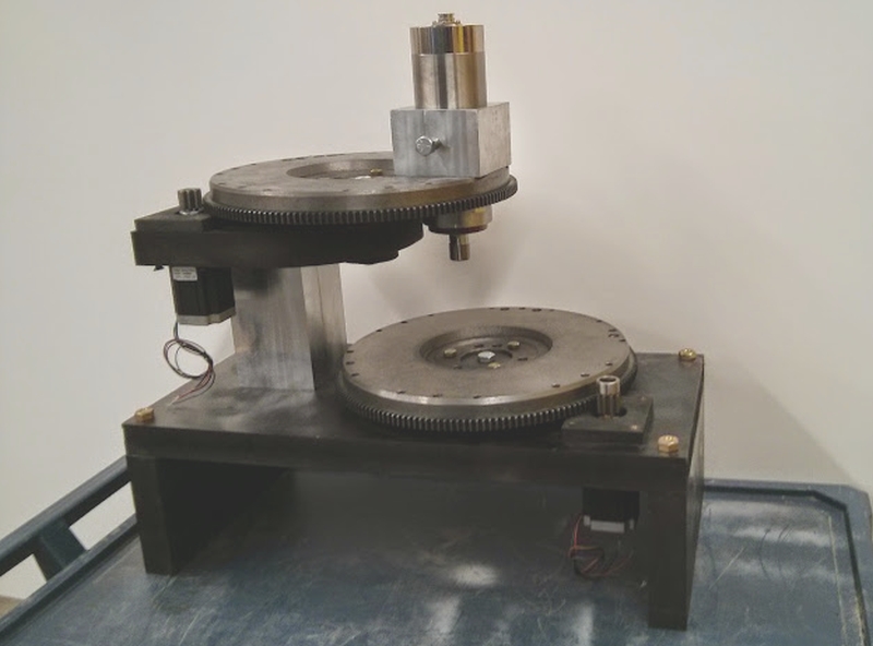
Whether 3D printer, lasercutter, or mill, most CNC machines use human-friendly, square-angle Cartesian geometry. This intriguing concept mill instead uses radial axes where motion is derived from scrap Chevy flywheels. It may look and feel weird at first, but it works – sort of.
Cartesian axes are intuitive. If you want to go to the right, increase X. If you want to go to away from you, increase Y. If you want to lift, increase Z. On a manual mill this is easy for making rectangles and blocks, or, with creative clamping, straight lines of any sort. But if you want to carve a circle? As we all learned on an Etch-A-Sketch, you increase your swearing and then throw it in the corner.
 [Jason] knew that with a CNC machine all geometry problems are reduced to math done by software. With two offset discs, any position is possible by rotating both the correct way. It may look odd that both plates drunkenly meander about just to draw a straight line but the computer is ambivalent. Software can be complicated without penalty and is free once written – more on that later. If a machine is physically simple then it can be built and repaired easily and cheaply. This design does away with almost all the familiar – and [Jason] argues complicated – components of normal hobby CNC machines. No slides, rails, carriages or belts here. His design uses only about a dozen parts.
Because automotive flywheels are made from cast iron the machine is rigid and naturally dampening. Sticking with the junkyard theme he pulled bearings from an F-450 truck, good for a few thousand pounds. Some steppers and a Raspberry Pi and he was done – well, sort of.
[Jason] let us know that his project has sat for long enough that he has become passionate about other things and decided to move on. He documented his progress and submitted the tip in hope to inspire someone else to continue the design further. Any type of CNC is possible, not just a mill. 3D printer perhaps?
Two big caveats: it needs a Z-axis (linear, probably standard) and there appears to be deeper-seated-than-expected G-code demands to chit-chat about rectangles and only rectangles. Nothing insurmountable, just nothing he has solved yet himself.
[Jason] said not to expect any further updates from him but he would love to see what the next person could do with it.
See the video after the break of the mill drawing our skull and wrenches logo, (soft of, without a Z-axis to lift).


Cast iron flywheel? Best jump in your Tin Lizzy and catch this morning’s Spruce Goose back to the reference library.
I … don’t get what these references are referencing.
Source article says: “The flywheels are cast iron”
But you just have to look at them to see that they aren’t.
Hint: cast iron is black
Machined cast iron has a grey/silvery appearance.
These are made from machined (probably grey) cast iron, car manufacturers don’t go straight from casting to bolting it onto a vehicle. There are intermediate machining operations between casting and assembly.
First, to disclose, I’m no expert. Are you?
Cast iron can take on several different appearances and the surface color is usually the result of high temp oxides created during the process. It’s almost all lighter grey deeper down. Also – stating the obvious but maybe I have to – not all cast iron is cookware.
Chevy does in fact produce cast iron flywheels en masse. The rough, speckled appearance you are probably familiar with on cookware and other parts is often absent on auto flywheels because their surfaces are ground flat after casting, resulting in a dull grey and smooth finish.
Also, the photo was dark so I brightened it so the structure was visible.
*shrugs*… as a general rule, unless I’m damned positive, I don’t like nitpicking a source author. If the guy says they’re cast iron, I’ll take his word on it.
For all I know they’re just plain mild steel, I doubt I could tell the difference by being an armchair expert whining about the pixels. Anyone reading this who knows more about cars that can provide something useful? I’m kinda curious.
back when i used to attend grasstracking events, i would often ask questions about the car builds, mainly carburated hatchbacks such as starlet, civic, micra. apparently it was quite common to lighten flywheels on a lathe to improve acceleration but from time to time this would cause the flywheel to fracture apart and breach the firewall so most were afraid to remove too much mass. that would tend to indicate that at least some were cast iron.
These will be cast from SG STEEL or SG IRON, its a higher quality steel and has a finer grain. They will be cast then machined giving them a normal steel look. So Yes they will be cast and not made from plate.
Looks like a pretty gronky CNC “Rose Engine” to me…
This was the predecessor to the SCARA platforms, and was slower given the inertia of each motion was high.
However, in the age of through-hole-parts this inaccuracy allowed one to wiggle pinned components onto the PCB. The current SMT standard usually relies on surface tension to align the parts.
I too, made a similar designed variant of this apparatus:
http://www.polarautomation.com/gallery/
One can only hope the kickstarter project didn’t just steal this guy’s work too.
Elektor magazine did a dual-head PCB drilling machine years ago based on this concept, I remember thinking at the time it was a really neat way of achieving motion. Bit like a SCARA arm.
The only image I can find of the drilling machine is this tiny crappy photo:
http://www.electro-tech-online.com/imgcache/5671-l010024-62.jpg.resized.0x200.jpg
The PCB is attached to a turntable in the middle and the two arms carry drilling heads. One of the purported benefits was the simplicity – no need for sliding bearings, just a couple of rotating shafts.
Oh… I didn’t think of that. I would seriously consider that for PCB milling. Or better yet… drilling. I hate hand drilling holes in PCB.
Oh yeah, that reminds me of the machines used to mill dental crowns: https://www.youtube.com/watch?v=7k3zttznjis
Such a neat design — the symmetric milling heads work both sides of the crown and balance out the torque. Looks like they’re using a combination of linear and rotary axes to do 5-axis(?) milling.
Excuse my English, I’m from Catalonia (Spain).
First, congratulations to Jason for its simple design and the reuse of parts, I love it xD.
I made a bipolar 3D printer like this project and the Theta-Printer. But the z axis it was with a linkage Sarrus (was not my best idea, but I wanted to try xD).
For the electronic used a arduino + RAMPS, since the processing of Gcode decided to do it on the computer and not on the arduino (for power calculations).
For the Cartesian-bipolar conversion I used a pluguin I created myself for CURA software. It is written in python and could adapt easily to make it independent of CURA.
If anyone wants, I can spend the code.
The calibration of these machines is much more complicated than the cartesian machines. A poorly calibrated deforms the piece to print. The arc than passing exactly through the center of the bottom plate.
I would like to know what maximum speed can move the dishes. With so much weight, inertia must be very large.
Good job
Yes, please do post the code! That’ll make it much easier for people to build polar-coordinate machines in the future. You’re right about the inertia of the flywheels. As I was building the machine I realized there are a lot of differences between mills for lightweight materials vs. steel — when you’re milling plywood, you want to move fast with a high speed spindle. But for hard metal, it’s better to give up speed for rigidity and inertia to reduce chatter.
I wanted to take advantage of these days to hang all the information on my website.
When I can upload everything in my site and I comment on here.
Were basically two files, one converting the whole gcode to absolute coordinates and the other made it to bipolar.
CURA plugins work postprocessing the Gcode. Read line by line and overwritten with the new calculated value. Therefore would have to be pretty easy code reuse.
In my code speed or acceleration is not calculated. Only is calculated x-y to tetha1-theta2. Therefore, the speed and acceleration will be the same as for the Cartesian movement. I print without any problem. Lie, slow printing problem in the center of the plate xD.
Now I posted a page on my website with the results. When I can would like to explain in another page the used code , but I am always very busy.
From my dropbox you can download the files.
For the cartesian-bipolar conversion are required only 2 files in the directory “cure plugins + conf”:
relative2absolute.py
cart2bipol.py
The other files are the settings for the 3D printer and a code that I tried to use a mechanical jack instead of Sarrus.
http://robertmenetray.com/impresora-3d-bipolar-con-enlace-sarrus
In the page is a video where you can see that the movements of the Jason machine are very similar.
What was wrong with using a sarrus linkage for one of the axes? Sounds like a great idea to me.
The Sarrus linkage is a great idea on paper. But the hinges have too much slack. I tried steel hinges and was disastrous. The best results were given plastic, but continue to have some slack.
This causes the layers become misaligned, although plastic hinges with the error is not so severe.
To ensure a linear movement of the current best solution is the linear bearings and linear guides. In its day I studied the solution of a mechanical jack to the Z axis, but also has problems.
Don’t listen to the haters. It’s about to be awesome so keep going!
Made something like this out of perspex back in 2000. Details at freeandeasy.sourceforge.net. Movies of the machine in action at http://freeandeasy.sourceforge.net/rotproto.php
It looks more like a fail of the week to me…
That’s an odd viewpoint. What to you is the fail?
He took a design part way to completion, and then documented it despite it having no advantage to him, then took time to get the word out so others could benefit.
How many projects end up half completed and their maker never shares?
The design hit some soft limits, like any project, and he just wasn’t interested in going further. There’s no catastrophe. There’s no arrogance or overconfidence and then disaster. Just walking away part way.
Partial success is success in my books.
Did you see the video and its output? It’s unrecognizable.
If you read his blog post, you’ll catch that he isn’t doing any coordinate transformation at that time. He was testing the two axis as polar coordinates just to test the mechanics.
And he quit, so how do I know it can do anything usable? There is one video,and that video fails to show any success, so to call it fail is sort of true, unless he finishes the project with success.
The video shows that the platform can work. There’s no doubt it’s only software away from working in polar coordinates.
How do you know if it can work? Hum, a bit of geometry; the two circular axes make it more difficult than just a simple r,θ conversion. θ is fine but finding r requires some changes to the coordinate bases (or vice versa, take your pick). Or, if you prefer, use quaterions. Seeing it move, and knowing that math works (it really does, I swear) and a little thought will show you that this does work and will work when someone good at geometry adds some conversion math to either the driver or to gcode.
And since when did we, the audience of hackers, start demanding that a hack “do something usable”? Fun shiny things are nice, so are projects that make you think more. Like this, which makes me think “damn, I wish I still remembered the quaterion math I learned for raytracers”, and may make others think “wow, no slide motors and bearings, that would be cheap if we knew the math” and some where in the middle we can all meet up and build some big SCADA type printer with junk-yard parts. Inspiration, if you like.
Not really Quin, for all we know the heaviness might make it always overshoot and the motor or drive belt might not be able to prevent that, and a host of other possible issues could occur, maybe the precision of the drive is not enough when working near the center of the wheel for another possibility., that’s the whole point of the ‘fail’ feature HaD has now, to show how unexpected and weird it can get when working on a project.
It could still be fail, you don’t know these things by wildly guessing
It can work and it’s been done.
https://www.youtube.com/watch?v=i6POrjVXgsk
Those are aluminium disks though.
Cool idea for source parts. There is a crowd funded printer that works with a jointed arm (and no turntable) to get a bigger print area from a smaller printer. But then there are how many crowd sourced printers out there? Yet none with a flywheel :-)
Is this it? https://www.kickstarter.com/projects/535786699/flxarm-low-cost-precision-robotic-arm
something like this?
https://www.youtube.com/watch?v=9_8dOvU_q6U&t=4s
“Software can be complicated without penalty” Oh god no…
Wooh wooh wooh. Taken out of context that’s an awful statement, yes.
What I meant was (summarizing Jason’s thoughts), that his goal was to simplify hardware and burden the software with everything else.
For example, trying to cut a circle on a manual mill is very complicated. But CNC is just spitting coordinates, it doesn’t care. The stepper motors are just reacting to pulses, they don’t care. Unless you’re flatlining the processor, keep shovelling the hard stuff to the software to do, rather than to a person or a mechanical design.
It’s spelled whoa.
– Ted “Neo” Logan
Thinking outside the box!
Sorry you’re not continuing. This would have been a good project for the hackaday.io
haaaaker
tybsn vyiw xkxnsvhbz
If it was me, I’d be drilling a whole lot of holes in these wheels to reduce weight, hence lower inertia, as well as lower motor torque requirement.
In other words, what you need is pretty much the opposite of what a flywheel is designed for, so not a great choice, but fixable.
You’d spend a fortune on drills doing that, and he’s using old parts to have low cost you would think.
If you drilled bulk holes in the bottom flywheel it would be then possible to thread these holes and use them for mounting purposes. Lower weight and inertia plus the benefit of flexible mounting.
just use flexplates for automatic gearboxes and stiffen them up by sandwiching the plate between two aluminium ones , job done
Screw drilling holes, he has a milling machine already attached! Mill sections out of the lower wheel, then swap it for the upper wheel and repeat!
I love the inception of this!
Hah, brilliant!
Very clever idea for the drilling of holes. I’d hate to be the one figuring out cutter compensation, though- it would hurt my brain.
This has great potential for low force CNC like a PLA printer or laser cutter.
I have been thinking of a way to make a cheap CNC miller / router. Conventional thinking is that rigidity is the key to repeatability and hence the conventional design using expensive linear bearings and rails to transfer rigidity through all 3 dimensions, from one to the next.
To explain – there are two purposes for linear rails in conventions designs:
1) The obvious – as a vector for the Cartesian system. In this aspect the linear rail is **NOT** providing rigidity or repeatability for it’s own dimension as that is done by the drive system for this dimension.
2) To provide rigidity for another dimension (not it’s own). This is the real reason for the expensive rails.
I want to solve the repeatability problem without expensive linear bearings / rails by resolving the rigidity to one axis (Z) by using a unique (and cheap) bearing assembly opposing free play in the Z axis. Then repeatability for the other axises is just a matter of the lack of free play **only in there respective dimension**. ie they don’t have to transfer rigidity to another axis.
For what I am intending to do (metal routing / milling) this dual rotating disk system isn’t suitable simply because I need much higher stepper rotations per inch that the disks can’t do without complex drive that introduce play.
However, for low force CNC this system is ideal and with a variation of the bearing concept that I will be using, it would easily achieve high repeatability with very low cost components.
Picture this –
Dimension 1) A MDF disk centered on a large diameter tapered roller bearing and driven by a synchronous belt on it outer diameter. The outer diameter also supported from underneath by two roller bearings placed as described below.
Dimension 2) A second MDF disk of perhaps the same diameter (that could be cut down to an arc) that carries the tool. It’s working range is from pivot to circumference of the lower disk. This disk also centered in a large diameter tapered roller bearing. The circumference of the second disk would intersect the pivot point of the first. The circumference bearings supporting the lower disk would be – one at where the the two circumferences meet and the other at the point on the circumference of the lower disk that matches the tangent of the intersection of the circumference of the upper disk and the pivot of the lower disk. Phew. The upper disk could have roller bearing supporting it from above. One each outside of it’s intersecting (work) range from circumference to pivot of the lower disk. Outside enough to leave room for the tool.
3) A normal Z axis for the tool.
This would be so cheap compared to linear rails and ball screws.
To me this is the (non)logic of linear rails –
Take ‘G’ clamp and cut it in half. Now G clamp horizontal bits of flat bar to each half. Now G clamp a third piece of flat bar vertically at the ends of the the other two so that the two halves of the cut G clamp are about where they were to start with. Now try to clamp something with the original G clamp.
A couple more flywheels and he’s got a 5-axis machine. I wonder if there’s any way to do it all with flywheels? You know, no linear z-axis.
I thought about this when I was writing…
A disc has 2 dimensions, X and Y. Two discs each have X and Y, and that’s why you can maneuver in that plane.
To add a third dimension, you get something funny happening. If you want to consider it a 2.5D machine, the vertical would have different amounts of precision depending on where you are in the wheel’s arc. Also, depending on how you did it, (do you attempt to have a linear slider that is depth controlled by a rotary edge?) it would move in an arc when lowered.
Think about how weird it is that, to just drill a hole, you’d have to be precisely moving all 3 discs.
With a 2.5D machine you’re still thinking Cartesian. Who says that square up and down in Z is the useful motion? Neither of the other discs move in a square manner.
I think it would make a fantastic art demo to simply mill a large square box out on a 3 axis rotary mill. It would do all sorts of fancy moving just to accomplish it… the way we consider that a mill has to do all kinds of fancy things to mill a sphere or some complex curve shape.
Maybe two more wheels to give you four axes and z capability. One to lower the tool, and another to choose the angle of the tool.
The problem with NOT having a linear Z axis is when it comes to drilling holes. Sure, the Z-axis motion can be non-linear, because you can compensate by moving the workpiece to compensate, but you have to be able to move a drill bit in a direction parallel with its own axis, i.e., it can’t tilt while you’re moving it up/down, or you either break the bit or grind out the sides of the hole you’re drilling. This can be done (keeping the bit’s motion “vertical”), but it requires 2 discs to handle the Z motion.
II dig it… The linear-bearing requirement for normal CNC is limiting. Definitely a lot of considerations come up that mightn’t’ve been thought of from the start… changes in precision based on its positioning, etc. Very interesting. Reminds me of my attempts with a hanging drawing-machine, with two pulleys and a lot of trigonometry. One thing I hadn’t considered ’till I ran into it was the fact that drawing near the pulleys meant that the two motors had to pull against each other, the torque increased dramatically toward the top of the system. Software fixed it. Though, the precision might’ve varied dramatically at different positions in the drawing-plane, hadn’t considered that. But this is the point of experimentation! Could certainly be useful if explored further. Momentum’s an issue, maybe reorder the cuts? Precision? What about DC motors with encoders? Vertical axis…? Maybe the bottom plate could be on a screw… These challenges are half of what makes doing stuff like this worthwhile. It would be *awesome* to see it draw a rectangle, and even better to see it cut a box.
Try such a plotter but with three or four motors and strings. With only two a major problem is sag of the lines and pendulum style swinging. You get poor accuracy in the lower corners due to sag of the longer line and the shorter line wanting to swing like a pendulum. It’s also a problem in the upper corners due to the weight of the longer line pulling.
Four motors and lines give full control authority within a quadrangle defined by the tangent points where the lines come off their drums. The big problem is balancing the tension. There are videos on YouTube showing an insanely fast 3D version using eight lines.
A compromise could use three lines, one each at a corner of the quad, and a fourth that is simply a weight hung over a pulley mounted like an upside down caster wheel so it can swivel to track the tool. To move the tool to the weighted corner, relax all three lines to their maximum. To move to the diagonally opposite corner, retract that line fully and extend the other two to maximum. That reduces the tension balancing control to just the two drives that are opposite each other.
This might also work using two weighted corners. With enough weight to keep the two powered lines taught at all times, speed could be increased a lot. You’d want some type of damper on the weights so they wouldn’t overshoot upwards when stopping a fast move towards the upper corners. You’d also want something providing extra downforce on the weights in case the machine is capable of unspooling line faster than gravity can accelerate the weights downward. Some long and light coil springs might do the trick.
With one or two weights the motion system wouldn’t be useful for milling, at least not for anything heavy, because any grab or kick would overpower the weights. (Unless it’s a really massive machine with extremely heavy weights.) But for a plotter or for a zero-force cutting tool like a water jet or plasma torch it would be a low cost motion system.
Since gantry type CNC has made them obsolete, pattern follower torch arms can often be bought very cheap. They’re built like a free moving SCARA arm. There’s a small motor at the top with its shaft centered over the gas torch or plasma cutter tip. The shaft is magnetic, usually diamond knurled. A steel pattern is positioned above the arm so the magnetic shaft can roll around the edge of the pattern. Very simple yet tended to be rather expensive in their heyday. (That would be early 1990’s and earlier.)
The pattern has to be 1/2 the diameter of the shaft smaller all around. Sharp inside or outside corners can’t be cut due to the shaft getting stuck on inside corners and the way it rolls around a sharp outside corner makes a curved point. If the shaft comes unstuck from the pattern you can have a rather bad day, especially if you need to keep waste to a minimum on a $1K sheet of 1/4″ stainless steel.
A cable drive CNC system for one of those torch arms would be mechanically simple. Just a square metal frame with the drives and weights at the corners. Put a washers at the other ends of the cables with holes the size of the drive shaft. Put the washers over the shaft and it’s hooked up and ready to do CNC cutting – once you have the non-cartesian software figured out.
One gotcha with such a setup is the arm’s maximum work envelope is very much non-quadrilateral. The controlled motion could be restricted to the largest quad the arm can reach, or figure out how best to use as much of the space it can reach as is practical.
So if you have a makerspace and want a CNC plasma table but are cringing at the cost, grab a math geek and find an old pattern torch, or build one.
Ah, interesting… I was trying to figure out how to use a a similar system horizontally… never came to idea of a third motor + counter-weight at a corner. I did, however, come up with a pulley-based system for pen-select and pen-up/pen-down, was pretty proud of that; each of the two upper-corners had two motors and two pulleys that move synchronously until a pen-select/pen-up/down operation was necessary.
https://sites.google.com/site/geekattempts/home-1/motion-control-and-legos
No idea what a pattern-torch is, but am intrigued.
Half the fun is finding out new ways to approach de-facto norms… gantries are cool, but things like this gear/polar system are really interesting to watch and contemplate, and interesting challenges too. (didja see the link someone posted of the pastry-cutter? Whoa. A floating gear between two belts and a stationary(?) water-jet)
Pattern Torch – awesome. Thanks! Even I could build one of those small-scale… Also, see that you posted the pastry-cutter, heh :)
Well, as long as we’re making it complex, why not go whole-hog and use an electromagnetic stylus on the Z axis to build shapes in magnetic sand (magnetite)? An automated sweeper could level it after each run to make an amazing art demo. The result would be rough because of the relative unpredictability of the sand placement, but with some (well, a lot…) of programming work you could perhaps create some really cool sculptures. Then, both the mechanism and the product would be interesting art pieces.
Polar coordinate pastry cutting with water jet https://www.youtube.com/watch?v=pmWSNqROYW0
LinuxCNC could be made to control this machine.
LinuxCNC (linuxcnc.org) is free open-source machine control that has interchangable kinematics modules. Kinematics is the math that lets you use non-Cartesean mechanisms. I don’t think the original machine above has been done in LinuxCNC yet, but several others have:
String based 2-axis machine: https://www.youtube.com/watch?v=oAyZxQSMNhg
String based 3-axis machine: https://www.youtube.com/watch?v=hrsDBdnj5E8
Hexapod: https://www.youtube.com/watch?v=hPE3Qr-ECtQ
Massive 5-axis machine showing how all axes move together to control the tool-tip location: https://www.youtube.com/watch?v=Nn1bJ3YAQdI
http://techref.massmind.org/techref/idea/lccam.htm