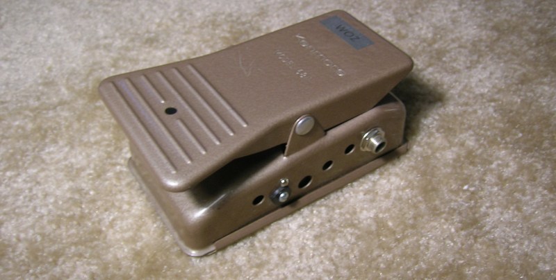
Rockin’ out on your fave guitar is pretty fun for sure but whether your on stage or jamming in your basement, it can be convenient to quickly mute those killer licks. [wozlaser] wanted a mute pedal for his guitar and instead of shelling out the tens of dollars for a commercial version, he decided to build one himself.
This pedal is heavy-duty and made out of metal. If the frame looks familiar, that is because in a prior life this was a control pedal for a sewing machine. [wozlaser] found it cheap at a thrift store. After the internals were taken out, he added a few key parts. First were the 1/4″ input and output jacks that were scavenged from an old stereo system. There is a momentary switch from a VCR and a standard guitar stomp pedal switch mounted all the way in the front of the frame. The wiring is as follows:

The wiring schematic is pretty darn simple, it just grounds and ungrounds the signal wire. As stated earlier, there are 2 switches, a momentary and a push-on/push-off switch. A normal mute pedal would only have one switch but [wozlaser] wanted something special. If you push the pedal all the way forward it will mute or unmute the signal until it is pushed again. When the pedal is in the spring-supported ‘up’ position a lever pushes on the momentary switch, a slight push on the pedal lifts the lever off of the momentary switch to mute or unmute the signal. The function of the momentary switch (mute or unmute) changes with the state of the other switch. This works exactly the same as a 3-way light switch circuit allows two switches to control one light in your house. With this setup [wozlaser] is able to not only mute and unmute his guitar but strum a chord with it off and pulse the chord on to the beat of the music or tap the pedal with some guitar feedback to make the sound cut in and out. All that only cost [wozlaser] a little time and spare parts… and there are no batteries to replace!


Switching noise will be pretty bad with this setup.
Here is an alternative circut that mutes by cut all audible frequencies with a LPF:
http://www.crownaudio.com/popless.htm
Could you please clarify this a bit? The way I understand it is that sudden shorting out of any residual DC component will cause a click/pop (as expected with a polarized condenser microphone). However any DC offset would be absent with a guitar pickup as a source – it is either just a passive coil or some sort of active circuitry with DC-blocked output. I guess the effect is pretty harsh, to soften things a bit I’d go for a LED-LDR combo!
I halfway agree with you. The link you sent shows an XLR balanced-input circuit, which would be different from the two-wire guitar line. Best I can tell, a number of commercial options like the Kill Pot or manually-added killswitches on the guitar body use the ‘route to ground’ method with a circuit matching the one in the original post. I have read that going that route can pop a bit, but I don’t know if it’s really much more than any other pedal pops.
I haven’t wired up one of these kills myself yet because I’m really not sure if shorting the circuit vs breaking it is the way to go (a volume pot turned all the way down would effectively break it, right?). I wonder which is safest electrically for the gear, and which of the options would pop the most.
My plan right now is to put my momentary switch on the pickguard and use the same basic circuit to ground it at the cable jack, but I’m still torn between circuits.
The pop doesn’t come from residual DC (which passive pickups don’t have and active onboard electronics shouldn’t have), but from the sudden transition a hard switch provides. You’re basically “chopping off” the waveform. Whether or not you actually find the pop offensive depends on many unrelated factors.
Shunting the signal to ground is certainly the only viable method, otherwise you’d be left with an imcomparably more noisy antenna. And no, the volume pot does not break the circuit, it’s a variable voltage divider.
If a simple switch simply will not do (and without going into zero crossing detection), a LDR could indeed be used, but also see R.G. Keen’s JFET idea described in this thread: http://www.diystompboxes.com/smfforum/index.php?topic=39660.0
whether you’re on stage*
looks more like a recycled hole punch.
well… looking at the above schematic, i’d call it PERM-A-MUTE(tm). what am i missing?
You missed “reading the article”… the switches are not linked and used independently.
yep, guilty as charged.