If you carry a cell phone with GPS, you always know where you are on the planet. But what about inside buildings or even your own home? Knowing if you’re in the kitchen or the living room would be a great feature for home automation systems. Lights could come on as you enter the room and your music could follow you on the home audio system. This is exactly the what [Eric] is working on with his Radiolocation using a Pocket Size Transceiver project. [Eric] started this project as an entry in the Trinket Everyday Carry Contest. He didn’t make the top 3, but was one of the fierce competitors who made the competition very hard to judge!
The heart of the project is determining Time Of Flight (TOF) for a radio signal. Since radio waves move at the speed of light, this is no small feat for an Arduino based design! [Eric] isn’t re-inventing the wheel though – he’s basing his design on several research papers, which he’s linked to his project description. Time of flight calculations get easier to handle when calculating round trip times rather than one way. To handle this, one or more base stations send out pings, which are received and returned by small transponders worn by a user. By averaging over many round trip transmissions, a distance estimation can be calculated.
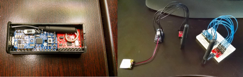
[Eric] used a Pro Trinket as his mobile transponder, while an Arduino Micro with it’s 16 bit counter acted as the base station. For RF, he used the popular Nordic nRF24L01+ 2.4 GHz transceiver modules. Even with this simple hardware, he’s achieved great results. So far he can display distance between base and transponder on a graph. Not bad for a DIY transponder so small if fits in a 2xAAA battery case! [Eric’s] next task is working through multipath issues, and testing out multiple base stations.
Click past the break to see [Eric’s] project in action!


I have been following the project since I first saw it, but i always thought the results would be pretty bad. The reason being that there are quite a few things that will introduce some randomness in the delay that don’t relate to the actual time(like how fast is the ACK sent after receiving the packet). But, i have to say that i am pleasantly surprised about the results. There is still a lot of work to do to improve it, but it is usable. I quick improvement would be to count pulses from an external clock source with higher frequency, 65MHz would top a 16bit counter in 1ms*.
I would be curious to see how accurate you can to this with the RSSI indication on some modules (lacking on NRF unfortunately).
*I don’t remember the max clock input for the counter in this mode, but I am sure it is reasonably higher than the microcontroller’s clock.
At least one of the white papers discuss RSSI (agreed on the NRF limitations), but they point out that drift or variance is a big problem with that method. I think it could be reasonably reliable for determining if you are within the immediate proximity of the base station, but has limited use at distance.
I mentioned this with Adrian below, but right now I have to ignore about 50-60% of the results due to a heavy amount of jitter seen in the response from the transceiver. I’ll see if I can put up a new project log this weekend with some screenshots to better explain what I’m getting.
The 130uS RX TX transition time can be extended if the nRF’s internal PLL doesn’t lock within that time. The nRF’s PLL is INCREDIBLY sensitive to high frequency noise on the power rails, that can come from either a switching power supply, or even from the MCU if bypass caps are inadequate. I had all sorts of trouble with the nRF, including dropped packets and sporadic timing, until I figured this out. I recommend soldering a 10uF SMD ceramic cap directly on top of where the VCC/GND header pins come through on the nRF module. That cleaned up the majority of problems, the addition of 1 ohm SMD resistors in serial with the VCC and GND connections (forming a low-pass filter with the added cap) cleaned up the rest.
Thanks for the tip, I’ll give it a shot!
Here is a way to get a cleaner sine wave out of a digital signal generator: http://www.edn.com/design/analog/4400342/Injection-lock-a-Wien-bridge-oscillator
Apparently the good qualities of different timing sources can be used to complement each other, thanks to the magic of loosely coupled injection locking.
While using time to ACK for time of flight measurement is an interesting idea, I don’t think that’s what he’s measuring.
Speed of light is 300M m/s, so he’d need a timer with at least 300MHz for 1m resolution (or 150MHz for two-way measurement). About 1 magnitude out of the Trinket’s league.
Even with a faster MCU/CPU, this approach is also limited by the internal clock of the nRF24. It will only process packets and ACKs with that time resolution (ignoring other things like TDMA or similar potential complications that limit the sending/receiving of packets to discrete time slots).
My guess is, he’s measuring the average number of dropped packets.
Here’s what i think happens(i have not checked the code): you want to measure some time that always falls under 1 clock period(assuming distance precision >TOF and should be perfectly fixed. Tmodule includes the time for the module to process the thole thing and reply, which is dependent on the 16MHz clock signal, it should have a nice predictable distribution. Doing multiple measurements means that actually Tmodule will dither TOF and allow you to measure it with a higher resolution than the clock period.
Assuming reasonably stable clocks, there wouldn’t be any dithering.. except for the phase noise in the clock transition areas.
jitter, not phase noise… I’m no RF expert. Just trying to think this through.
You have 2 clocks that are not synced, one at the sender and one at the receiver. Once the packet is received, the processing will start on some edge of the internal clock. But the packet always lands with a random position in respect to this edge causing the delay to have a random part.
Good point, I was only considering the senders clock.
If random, then it is a white noise dither. What does that average? Does not converge?
[TheRegnirps], an example of how this works:
1) Take 1.3. Assume you can measure this only to the nearest whole number. The result is always one.
2) Take 1.3, add a random value from -0.5 to +0.5, measure to the nearest whole number. Do this 1,000 times with a different random value each time. Average together the whole number results, and you get a result very close to 1.3.
Under the right conditions, injecting a little bit of randomness actually lets you measure things with better accuracy. Amateur astronomers use this technique to take digital pictures of things so dim they barely register on the imaging sensor, even with the longest exposure. They take a bunch of pictures and average the results. The randomness is produces by the CMOS sensor elements themselves.
This is the best explanation I’ve been able to come up with, personally. When I first started the project (and can be read in some of the early logs) I began to doubt if it could ever work because of the limitations of the clock speed of both the MCU and the transceiver. However, it appears that due to slight variances in clock frequencies and possibly even multipath variances in the transmissions, you end up with enough dither (thanks for that term, I’ve had a hard time coming up with a way to explain it!) to achieve sub-clock measurements.
That said, you have to keep in mind that I’m often performing m,ore than 500 measurements… trying to trim it down to just a couple hundred provides results with way too much jitter to use.
How about external counter with external clock source in the base? That way the dongle can still stay the same.
I’m trying to keep component counts down to a minimum. The micro actually has the ability for a pretty high resolution counter; I’m just not making use of it as I don’t want to limit the base stations to just a handful of boards. On the transponder end the MCU is actually just keeping the RX buffer clear and doesn’t handle it on a packet-by-packet basis. Doing this method means the transponder MCU can actually be pretty mild and have a very slow clock to minimize power consumption, but I’m also operating in RX mode which draws more power.
Eric here! By all means, you’re absolutely right. To really, accurately, measure the TOF I need a timer that has much higher resolution than what I’m using. Right now the project is clocking the timer at 16 mHz, although I can get up to around 60 with the micro; if I recall correctly it can be clocked off the PLL clock. However, I’m trying to stay around 16 as it expands the capability for this to work outside of just a handful of Arduino platforms.
The clock speed of the transceiver is definitely a challenge as well with results often falling between one of two ranges, and with small variance of only 10-20 clock pulses amongst them. For instance, on some recent testing I’ve got a range that centers around 12740 clock pulses and 12865. Amongst these ranges it’s about a 50/50 split for the results. At 16 mhz that should be 796-804 us which is inline with what the Nordic datasheets indicates transmit time should be, but I haven’t come up with a good explanation for why there’s that much spread between results; it’s certainly created by the transceiver, however.
Some initial testing was based around dropped packets, but it proved very unreliable as changing environments and whether you were holding the transceiver or sitting it on a surface had a large effect on the results. Right now I’m still trying to find a better way to average the results as at the moment I have to drop about 50% of the measurements to focus on one of the two ranges. Some rough attempts to average both haven’t turned out very well.
The code is written such that if I do get a failed transmission, it retries again so all of my time measurements are based on successfully acknowledged packets. Typically to get 500 successful packets it takes around 550-700 attempts depending on the range and environment.
I do think that resolution is still going to be lucky to fall under the 5m range; with that being the best both of the white papers have shown and falls pretty close to what I’m seeing. That said, I’m willing to accept that, but I want to cut down on the drift considerably.
That’s kind of the maddening aspect of this project… it really shouldn’t work in theory due to a handful of reasons and I’m having trouble coming up with an answer for why it works at all.
“The clock speed of the transceiver is definitely a challenge as well with results often falling between one of two ranges, and with small variance of only 10-20 clock pulses amongst them. For instance, on some recent testing I’ve got a range that centers around 12740 clock pulses and 12865. Amongst these ranges it’s about a 50/50 split for the results. At 16 mhz that should be 796-804 us which is inline with what the Nordic datasheets indicates transmit time should be, but I haven’t come up with a good explanation for why there’s that much spread between results; it’s certainly created by the transceiver, however.”
I suspect this has to do with how the measurement of the 130us needed for PLL sync which is given as a max value.
Holy crap, thank you very much! That never occurred to me. If that is the case, and it appears to be, that gives me the use I need to combine the two sets of results.
-use +offset
in your example there are 8us difference between the 2 values. So maybe the PLL is checked for locking every 8 us. If you deduce this value then it is possible to correct for it in software.
Yup, you’re right. I was confusing clock cycles for raw time.
When you transmit(without auto ACK) you can get an interrupt when the TX is completed. If you do manual ACK you cand transmit in you next packet the time it required to send the previous one, which would include the PLL settle time. So you can correct for it..
“I suspect this has to do with how the measurement of the 130us needed for PLL sync which is given as a max value.”
130us is a MINIMUM, and enforced regardless of whether the PLL locks faster. Otherwise you’d have some nRF’s that naturally sync faster than others, and sending responses before the other side is ready to receive; which would be a complete mess. It can however take longer than 130us to sync if there’s power supply noise – which I described in a comment further up.
I remember you mentioning that before. I can understand why you say it is minimum, but then the datasheet specifies this time as maximum.
Funny thing, I see that in the datasheet of the NRF clone, the RFM73 you can actually set the PLL time as 120 or 130us.
Yep, the datasheet does say maximum. I’m fairly confident this is just misworded. I was really hoping I could get faster lock – at least between certain hand-picked transceivers used as designated repeaters in my mesh network – but have never been able to produce a lock time under 130us. Conversely, I saw one fellow reporting his module took several ms to lock and start transmission, probably due to power supply noise, although it may have been faulty.
Sorry I haven’t looked at how you are doing the TOF calculations but there seems to be a way that for 4 ms you could bypass the wait for the PLL lock before each transmit (it only only need to lock once) as the nRF24L01 datasheet says: “The nRF24L01+ transmitter PLL operates in open loop when in TX mode. It is important never to keep the nRF24L01+ in TX mode for more than 4ms at a time”.
So if I read that correctly, you keep loading packets into the FIFO (shockburst may need to be disabled and also auto ACK), on the RX side you could just listen for the first packet by checking RX_DR or the IRQ, but don’t read it out, start your timer, flush the RX packet and then note the timer value when the next packet appears and repeat. But you are only limited to 4 ms (or more if you wish to take it further).
This has to do with the case where the radio cand transmit packets sequentially wothout a break. In that case you should not transmit more than 4ms. I don’t think there is a way to skip the 130us when starting to transmit.
Alex,
In my particular case I send a junk packet (just one byte, don’t care what the value is) and then making use of the Reuse_TX function. At that point I can either hold the chip enable pin high or pulse it to repeatedly send packets without needing to reload the buffer. I am currently holding the chip enable high for two consecutive packets, but it appears to still perform the PLL lock as my time from start to the first packet and from the first packet to the second are nearly the same length (about 843us for the first packet and then 790us from the time the interrupt is read and second packet flies out). Granted, loading packets continuously into the TX buffer may behave differently.
On the receiver end I’m actually doing very little with the MCU; just checking and clearing the RX buffer as necessary to keep things going (if the RX buffer fills, it’ll stop receiving). Typically this is only a problem at long distances where packet loss becomes a problem. Otherwise, the transceiver on the receiver end is handling the auto-acknowledge and I’m just checking the buffer every 60ms or so.
Hi Bogdan & Eric,
I decided to test the TX side (only at this stage), load 2 packets, 5 byte address and 1 byte payload, running at 20MHz.
Here’s how it looks like – http://i.imgur.com/H8PWfNP.png & http://i.imgur.com/qMY41Lp.png, we’ve got 165 us from CE to IRQ low, once IRQ is low, I reset the TX_DS in the status register so IRQ goes high and then it goes low again much quicker (32.5us from low to low which is consistent), so it does look like the PLL doesn’t need to lock again in this case. Could you try on your TX side and see if you get similar results?
[Alex],
What you’re describing is correct, but only if you’re NOT using the Shockburst feature of the nRF. Shockburst adds auto-ACKnowledge, auto-retransmit if ACK was not received, and variable size packets. ACK is sent by the recipient after every packet, thus the recipient must switch to TX to send the ACK, and the original sender must switch to RX to hear it. If you’re sending two packets back-to-back, the transmitting side must go from RX-TX-RX-TX-RX. With the 130us PLL settling time incurred for every transition.
Yes, this is very inefficient if you’re going for speed and bandwidth. In my own mesh network implementation, where I typically must send more than one packet, I disabled Shockburst and instead have the MCU generate a single response only after all packets are sent.
But accurate timing is what’s important in this project. Since the time involved in flight of the signal is so small, it must be accumulated over many rapid back-and-forth transmissions, then averaged, to be measured. Sending multiple packets back-to-back with no PLL settling time would not be beneficial in this case. For a single-direction transmission:
1) For one packet, total time is 130us + packet_tx_time + TOF
2) For two packets, total time is 130us + packet_tx_time*2 + TOF
You can see each transmission, regardless of the number of packets sent, only measures the TOF once – since TOF is related only to distance, not the size of the payload. You need another transmission (the ACK), going in the other direction, to measure TOF again; and for that the 130us wasted time is unavoidable. Multiple back-to-back packets only slows things down. In addition, if we wish to send a single ACK for multiple packets, the MCU would then be responsible for that; and it cannot accomplish that as fast or with the deterministic timing that the nRF can with auto-ACK.
Still, you deserve +1 for trying to figure out a way to improve this. It’s quite an interesting project. Since reading about it I’ve been racking my brain, trying to figure out how to integrate similar functionality into every node of my mesh network, without interfering with the existing functionality.
As described, I don’t think it’s measuring dropped packets. Auto-ACK is on, auto-retransmit is off. So both the packet and the ACK go through on the first try, or the attempt times out completely and should not be factored into the TOF average.
You’re right, even at 3M resolution this should require a ~100Mhz clock to produce, which neither the Trinket or nRF have. But I think there’s still a way this can work. (I see a lot of this is already covered since it took me a while to type and proofread, but I’m posting as originally written anyway.)
The clocks for each nRF aren’t running at *exactly* the same rate, nor are they synchronized to each other. Assume a fixed distance, and exclude all other factors which might affect timing other than the clocks. How many clock cycles does round trip take? Might be 4,012, but due to the unsynchronized clocks, it might sometimes take 4,013; with the distribution between the two values based on what the physical trip actually takes. In reality the results are going to be far more varied, but the point is that by averaging results together, you get some degree of sub-clock cycle measurement.
I also note that the Trinket Pro runs at 12Mhz, and the nRF has a 16Mhz crystal. Since the lowest common multiple between the two is 48Mhz, that means the Trinket is theoretically able to recover timing info up to that higher rate through averaging. It might not work so well if the Trinket was running at 16Mhz too. And it might actually work better if the Trinket was running at 13Mhz.
I’m very tempted to try this. The PICs I use have an “input capture” peripheral, which saves the clock value in response to an incoming signal (interrupt), which would make this easier.
Actually, in my case I’m only using the Trinket Pro to manage the RX buffer and it’s not taking part actively receiving every packet; just checking the buffer every 60 ms or so. So in my case I’ve only got three clocks actively taking part: the base station, and both transceivers. All three are at 16 mhz.
I had pondered trying to mix clock rates previously, but didn’t have the time to venture through it and I still wanted to keep involvement of the RX MCU to a minimum to save power and reduce sources of error.
Back in the day, when one needed to profile a function to see how fast it was, but the function executed far faster than the millisecond timer we had available, we would record the time before and after the function and average the results over several hundred runs, or we’d record the start time run the function 1000 times and record the end time.
It seems to me that if you want to record how fast a light pulse returns, you don’t need a processor that’s 150MHz, but rather a circuit that can work at 150MHz. In other words, if a returning pulse of light can retrigger another light pulse automatically, and you can count the number of pulses, and only report back the time it took for 100 to occur, then you only need a processor that can handle a 1.5MHz data stream to process that data, and only your transistors controlling the pulses and the counter need to be able to work at 150MHz.
Initially I tried a method like this, but ultimately because you have to wait for a clock cycle to begin another step and it ends up eliminating any accumulated TOF. The results I got showed very little variance and I ended up trying to battle how to account for lost packets which I didn’t have the time to fully resolve.
This TOF calculation is supported by some NXP chips too. The basic idea is to set up a ping pong between two receivers that runs in a fixed amount of time. This has to be an absolutely fixed amount of time so it is common to use hardware for the ping pong. Next you send 100-200 packets into the ping pong and measure how long it takes. The excess time required is the speed of light travel time. Do the math and you can get the distance. Drop packets spoil the result and you have to start over.
So 12ft is an excess of 200* 12ns = 2.4us, 11 ft is 2.2us, etc. If 0.2us is too small for your CPU increase the number of ping pongs.
Major downside of this technique is the battery draw. Maybe some day BLE will get the AOA (angle of arrival) hardware that has beeb talked about for several years.
This was how I first tried approaching the problem, but found that I was limited by the clock speed on when a packet was received and another was triggered to begin. Waiting on a clock cycle ultimately eliminated any accumulation of TOF. How I’m approaching it right now is measuring the time from when a packet is sent to when the auto-acknowledge is received and averaging those values.
I don’t have access to the internals of what NXP is doing, but it seems like they are using the auto ACK hardware to achieve 200 round trip pings with no software intervention.
You might be able to simulate what the NXP chip does. Put code in the auto-ack interrupt to retransmit as soon as possible for 200 RT. Measure the time for the complete 200 round trips instead of measuring the trip times individually. Maybe even use a hard loop looking for that auto-ack and then retransmitting.
A key issue to to use something like the highest priority fast interrupt so that the ISR processing time is stable. This is equivalent to what NXP does, but they can retrigger the transmit from the packet state machine without the need for an interrupt.
I like it! I have been wondering on and off for years about timing for an RF network for a collection of remote microphones to make a “sound camera” on a big piece of property. Synchronizing kept getting complicated. Solved (and cheap)! For sound this if practically overkill.
[Maxzillian], I see the project uses “a 250 bps transmission rate” (which I assume is a typo and 250Kbps was meant). This gives the best receive sensitivity for the nRF, good for when you’re running this out to 40 feet. But I’m curious what effect running at 500K/1M/2Mbps has. Since exactly how this works isn’t fully understood, there’s a possibility it might increase resolution. Have you tried this?
I should have mentioned 500Kbps is selected by setting RF_DR_HIGH to ’11’. It’s undocumented, the datasheet just says that value is “reserved”. But it is an option, works and times as expected, and I’ve heard it has been successfully used to communicate with older Nordic transceivers which officially support and were set to 500Kbps.
That would be a typo. It has been on my list to try the higher transmit speeds.
Or you could use a ble nrf51822 wafer package that is about 2mm^2 and uses a hell of a lot less power…
Could, yes, but with the Trinket Everyday contest I was pretty limited to what MCU I could use. Part of the aim with my project was to try and use off-the-shelf breakout boards and components so it could be replicated by anyone of any basic skill.
Cool, set a few more of the base stations up, and do some triangulation algorithms; IPS (indoor positioning system!).
Dang! And here I was happy with my results using TDOA of RF and Sound, having a bot beeping a high frequency sound every few seconds. Back to the drawing board, now I need a silent version (or just go ultrasonic and have the neighbourhood dogs on my case)
Too bad UHF RFID is still expensive. In my old company, they were trying to do tag positioning by using multiple antennas and RSSI measurement. It was possible to get a relative measurement of distance by using RSSI but not absolute. I guess that by using fixed tags in some places and one mobile tag on you and by comparing the RSSI signal from all of these tags, you should be able to do some approximate positioning inside your house. Enough for an home automation system at least.
The problem with UHF RFID is that it is very sensitive to the material. And also to the position (there is some omnidirectional tags but they are less powerful, see Frog 3D etc…). And it’s loosing all signal when close to liquids and/or flesh.
Really good discussion round!!! I have using a similar aproach using RSSI with https://lowpowerlab.com/shop/moteino-r4 and https://lowpowerlab.com/shop/index.php?_route_=all-products/RFM69HW module that is a pretty similar platform but with more power/distance RF module option. Also you can check a related point in http://hackaday.com/2011/03/21/rf-range-finder-doesnt-need-to-see-to-calculate-distance/
I haven’t thought this through or read enough of the documentation to be sure it’s not just a stupid idea, but …
Is there any way to operate ‘full duplex’ with the far end echoing received data while still receiving. I assume this needs two nRF24L01s per end and probably some extra hardware as well, but maybe not. With a receive diplexer you can perhaps use a single antenna per end but, by gating the RX or TX at the RF level you may be able to create multiple ‘messages’ without pause out of a single transmission. It may be that the 24L01 is in fact more complex than is optimum for this task and that a ‘dumb’ transmitter + responder that sent back bits on a bit by bit basis when triggered by an incoming bit may be more useful. This could be as simple as sending a stream of ‘bits’ and averaging the phase / time shift of the received stream. Bit width at tx needs to be < ( 2 x tof + response time) for no tx/rx interference (assuming tx is off and rx channel open between bits.) Response time can always be made longer :-). This is akin to classic "Break In" morse code operation where operators can listen between their transmitted symbols for responses.
… Agh – rereading notes I think that is exactly what you and jonsmirl were discussing … However, does there need to be any "waiting on a clock edge" that you mention? If the received RF envelope (using an AM analogy to start) gates the re-tx signal you get a retransmitted signal delayed almost only by signal path related delays. ie you never get out into the true 'digital' environment and the send end receiver is essentially comparing say two leading edges for timing differences.
Russell McMahon
apptechnz@gmail.com
I’ve heard of this approach. Basically you’d need a separate TX/RX (full duplex) for each end. Each RX would need a pin with direct digital output of what it’s currently receiving (gated from analog as you described). Each TX would need a pin that controls the current output. On one node, you’d need to just tie RX output to TX input. On the node where measurements take place, you’d either:
1) Change the TX state and wait until the RX state changes/matches, measure the time elapsed. Would still be very small, so it’s usually more practical to…
2) Tie the TX state to the RX state via an inverter, creating an oscillator involving all four radios, which runs at a frequency related to the TOF. Passed through a prescaler, this can be measured easily by an MCU.
Unfortunately I don’t think this is possible with the nRF24L01+. As you suspected, it’s too complex a radio. Everything is always packetized. At the same time it’s also too simple in a way, lacking low-level diagnostic facilities that we might take advantage of. The only special mode is to transmit an unmodulated carrier, for purposes of measuring power output. Which having no RSSI facility, can’t even be detected. (It actually does have some RSSI capability, but it’s merely a flag that says whether the last complete packet received was above or below -64dBm; so limited most people consider it to have no RSSI at all.)
This is what the promised BLE vaporware hardware does…
http://www.analog.com/en/rfif-components/detectors/ad8302/products/product.html
Some future Bluetooth generation is going to support that phase detection in every chip.
You hook two antennas up to your base station with AC power. A chip like the AD8302 then gives you an output corresponding to the phase difference of the received signal at the two antennas. With two base stations in known fixed locations you can do some math and get pretty exact locations of a third, moving device.
Of course there is nothing stopping people from hacking together a base station based on this chip. Alternatively, I wonder if it is possible to hack on some MIMO wifi hardware and build a phase detector?
The math is simple triangulation. Since you know where the two base stations are, and you know the angle from each to the target transmitter, just finish the math for the triangle.