Since the Raspberry Pi 2 was released, everyone building RetroPi emulators has been graced with four USB ports. For those of us doing useful stuff with the Pi, those ports are a little anemic: you can’t plug in a webcam and a WiFi module at the same time without suffering CPU brownouts. The maximum current all USB peripherals can draw from the USB port is 600mA. By changing a value in the /boot/config.txt file, this current limit can be increased to 1.2A for all four ports.
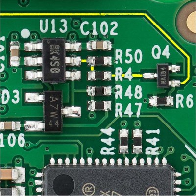
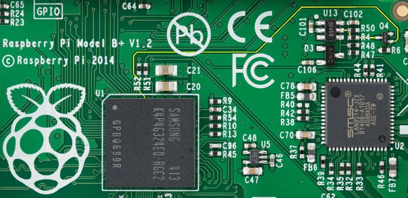
Because the USB current limit is set in software, there must be a few bits of hardware that do the actual work. Tucked away below the right hand of the GPIO header is the hardware that does exactly that. It’s an AP2253 current-limited power switch (PDF), and the current is adjustable by tying a resistor to pin 5 on the chip.
Pin 5 on the AP2253 is connected to two resistors. One resistor goes directly to a ground plane, while the other is switched through a FET. The gate of this FET goes to another resistor, and when a GPIO pin is high, these resistors are wired in parallel. This means the resistance is halved when the GPIO pin is high, doubling the current limiting circuit in the AP2253.
This setup provides a relatively easy mod to increase the current limiting of the USB ports so they can provide 4x500mA, meeting the USB spec. The AP2253 power switch’s current limiting can be set by a single resistor, anywhere from 10kΩ to 232kΩ. By removing R50 and R4, and replacing R50 with a 10kΩ resistor, the current limiting of the AP2253 switch will be set to its maximum, 2.1A. Divide that by four, and you have 500mA per port, just like every other computer on the planet.
There is a reason the Raspberry Pi foundation set the current limiting of the USB ports so low. The Pi was originally intended to run off of a micro USB phone charger. There aren’t many phone chargers out there that will supply more than 1A, and the CPU and related peripherals will take half of that. If you’re going to change the /boot/config.txt file, you’re going to need a beefy power supply. Increasing the current limiting of the USB ports to 2A will require an even bigger, beefier supply.


1.2ma? should be 1.2A
1.2ma? should be 1.2A… Absolutely it should.. But everybody makes a typo now and then… What’s more critical though is if you do increase the output that much, then a 2A or even 3A PSU is essential. I consider a 2A PSU a must have on the new Pi 2, before you even start adding USB peripherals and a 3A one a very good idea if you add more than a keyboard and mouse. The new CPU and Memory chew more juice than they claim, when they’re working hard and if you over clock them as well then 3A power is absolutely a must have, to cope with peaks.
Has anyone looked at doing this with the OG Pi Model B?
The original model B doesn’t have any of this. The power circuitry is much simpler and it is basically limited by the main input polyfuse and the USB port polyfuses if they exist on your particular revision of the model B.
off by 1000 error :) 1.2ma instead of 1.2A or 1200mA (line4)
Great hack BTW :)
Just for clarification, is the resistor swap needed in addition to the config.txt change or is the config.txt change sufficient to enable higher current?
All the information is in the article above:
1> Default maximum 600mA total shared between all 4 ports
2> Modify /boot/config.txt maximum 1.2A total shared between all 4 ports
3> Hardware hack 2.1A total shared between all 4 ports.
All this assumes that the power source supplying the RPi2B is providing this power plus enough to power up the RPi2B board.
If you want more than 1.2A then you need both.
Wrong if you want more than 1.2A just the hardware rework is needed. By removing R4 that disables the pi’s control of the current limit and R50 sets the max current all the time.
Now THAT explanation makes sense.
Or you could read the AP2253’s datasheet (conveniently linked in the article) to verify that lower resistance = higher current limit, understand what parallel resistors mean, and only change the software-controlled one so as to keep the software control and simply change the “more” setting to mean “all the current”. This allows you to sacrifice some USB capability later on if you have to use a smaller supply, without modifying the board again.
That’s a great idea. Can someone confirm that R50’s value is 36k? If so, then replacing R4 with 13k would yield a current limit of 2A – 500 mA x 4.
Of course, now you’re on the stick for providing just under a potential maximum of just under 3A @ 5V. Good luck with that. :)
+1 sanity points to you. No reason to modify three resistors, unless you’re going to remove the FET too and repurpose the GPIO pin.
Old thread, I know, but I’ve just done exactly that…
I’ve had my RPi 2 B running as a lazy fileserver with a couple of portable USB drives, but the oldest/smallest one would get suspended & irretrievably disconnected due to overcurrent if both were accessed at the same time.
On my unit both R50 & R4 measured 39k, giving (according to the datasheet) ~550mA normally, or 1.1A with “max_usb_current=1” set. Replacing R4 with an 18k resistor – giving 39k||18k = 12.3k with “max_usb_current=1” set – upped that to a calculated ~1.75A & solving my problem.
And for the benefit of any future modders: both R4 & R50 are 0402 SMD resistors, which is not a size I normally use. However, if you’re careful there’s enough room to easily fit a 0603 in there using paste & hot air (the 0603 covers the 0402 pads, so hand-soldering the larger size will be difficult if not impossible).
Neat hack :)
The Pi is a good board to cut your teeth on, at least from my experience. That said the way they handle the USB, between the power issues and the fact that they are still lumping the Ethernet onto the USB bus. Personally it has become a deal breaker for me. Especially when there are more cost effective SBC alternatives on the market.
Do you have a SBC you recommend instead of the RPI? Genuinely curious in a cheaper alternative.
….. One of these days I’ll start a reply on HAD without hitting the report button because their report button is where every other web site I go to has their reply button. Until then as per standard please ignore that report D:
Off to a good start eh :P
I’ve been leaning towards the Odroid C1, Both the Pi and the Odroid push themselves as $35 SBC. Tho because of vender markup neither of them really hits that exact number. Where I live the Pi typically goes for ~$40 and the C1 goes for ~$38. Personally to me that is close enough to consider them effectively the same price.
Where I consider it to be more cost effective are things like the built in RTC. I had originally purchased an I2C for my Pi which works fine but also set me back another ~$10-14 (maybe less if you snag a super cheap one off eBay). If you have a constant network connection for the Pi it probably isn’t going to matter much because the Pi will just snag the date and time off the internet. Unfortunately neither of my projects can guarantee the SBC in question that luxury and require the system to know what the date and time is either for schedualing or consistent timestamping.
Then there are other perks like being faster 1.5ghz(C1) vs 900mhz(Pi2), tho in fairness my PiB is one of the older 700mhz models and still works for most of my applications. I’m just going with the updated clock for closer comparisons sake. The C1 also has Gigabit Ethernet and not only a slot for MicroSD but also socket for eMMC, none of which are on the USB bus (I can not stress how much I appreciate this fact). The eMMC isn’t necessary and definitely not cheap :P So you can always just go with a MicroSD. If boot speed is important and for one of my projects (an ROV) it is. If I end up needing to reboot for whatever reason and it happens to be lets say at the bottom of a lake, I’m probably going to want it to boot as fast as is humanly possible. The nice thing is you can let it boot from an eMMC and it can still address a MicroSD card. Which means you don’t need to go with the biggest eMMC you just need one big enough for your OS + a little wiggle room (updates etc) then let the much larger MicroSD card handle the day to day data logging/storage/etc.
I apologize, I sorta started rambling :P
For me it ended up being more bang for my buck.
There’s also the Pogoplug 4, which goes for about $19 with USB3+SATA and $10 without. Note that the version with USB3 also includes a larger (2A vs. 1A) PSU. Both have standard Gigabit Ethernet.
I had considdered the Banana Pi for a while because it too supported SATA and the potential extra storage capacity was alluring to say the least. Unfortunately it was only dual core, more expensive and didn’t have a built in RTC.
I will be honest I haven’t heard of the Pogoplug until you mentioned it and I am having a bit of trouble tracking down specific tech data this morning (not too much time to look). Does seem like it can be modified sufficiently to do some interesting stuff and at that price I’ll definitely look into picking one (maybe two) up if for nothing more than seeing what it can do.
Would you mind listing some of those “more cost effective SBC alternatives on the market”? Thanks.
It really depends on what you are trying to do and what you need and what you can live without. I have found that the bulk of my current projects need an RTC as they don’t have access to the internet to snag/update their date/time settings. So a SBC with a built in RTC is a big perk. Faster Ethernet that isn’t potentially fighting for bandwidth over the same bus as multiple USB cameras, while trying to stream video from said cameras. Multiple data storage options that don’t compete for USB resources. Some more ponies under the hood, etc.
So for me a Odroid C1 was more cost effective even tho the base price of the Pi and C1 are close enough to effectively the same.
If we do the modification mentioned above, but additionally connect the (now open) drain of Q4 to pin 3 of U13, then we can use the GPIO to switch the USB power on and off.
Imagine all sorts of USB powered gadgets being switched via web, bluetooth, touchscreen, timer, etc.
Good idea, this would also allow you to conserve power if you are building a battery powered Pi, you would be able to switch off the Wifi or 3G dongle and only wake it up when needed. I think this should be fed back to the Pi team so it can be incorporated in Pi2 rev2
Or a two position jumper.
One position for stock behavior, the other you add your own resistor or trigger.
In theory, those USB compliant peripherals would honor USB power management (suspend/wakeup) without hardware mods and you can selective power down devices instead of everything.
Not if you use “passive” USB powered devices, like lamps, ventilators, shoe warmers, sex toys, etc.
Nobody ever thought “Hold on while I whip out my Raspberry Pi and my sex toy” was a turn on. *rolls eyes*
You must be new around here. This is the internet we’re talking about, I’m sure someone somewhere has already done it.
Rule 34. No exceptions.
Hagfish slime fetish. There are exceptions to Rule #34, they’re just few and far between.
Sometimes you might want those toys to be controlled wirelessly, so turning *everything* including your USB wireless dongle off kind of limits your application You are far better off using GPIO to control the non-compliant passive devices separately.
Ever heard of wired Ethernet?
I know, it’s old-fashioned.
FYI: Micro USB connector per USB spec has a current limit of 1.8A, so the manufacturers are building them with that specs in mind. As usual some charger vendors might be more conservative while others are cutting corners. The quality of the wire in the cable are going to be more critical as there will now be twice as much I*R drop.
BTW, the USB specs doesn’t say the PI *must* provide 4*500mA power.
“For those of us doing useful stuff” – wow, nice dig there. I’m thinking of making a new entry into the Urban Dictionary.
Benchoffing, verb. To show disgust for someone’s use of their own time and resources while enjoying their hobby, usually involving an Arduino or some other project, like a RetroPi, that Brian Benchoff has deemed useless.
I share the same opinion Jeremy,
Don´t know Benchoff’s background and history, but find myself more and more negatively impressed every time he comments on his own posts at Hackaday.
I also don´t know how he can hold a professional life based on that sarcasm and extremely dumb self-confidence.
ha, touched a nerve did he? :)
And you should quote the whole line: “For those of us doing useful stuff with the Pi,”, so it’s not anti-pi but more a admittedly odd way of saying that he thinks the Pi is useful if you use full power from all the USB ports, which is an rather peculiar definition of useful
Always wondered why mini usb for power on the Pi. I know it’s a universal (or should be) standard, but I like the flexibility I get from my arduino UNO allowing either USB or brick power supply to be used. Anyone seen a hack with a regulator that incorporates a 5VDC supply?
It’s micro USB, but thanks for playing.
You can power it from gpio pin’s
thanks. Did not know that bussing power on the GPIO pins was an option.
i used a ubec i had left over from my failed r/c aircraft hobby. it can output 5v, 3a. though i had to rearrange the pins in the header to match the pinout.
At the risk of being a bit of a spammer, I’d like to humbly mention my solution to the problem: Pi Power. It’s a DC-DC (buck) converter that sits on the GPIO pins and supplies up to 2A @ 5V with anywhere between 6 and 14 volts DC in. It comes with a stacking header so you can plug other things into the GPIO header. That in and of itself is a good solution for plus owners that have 24 pin ribbon cables but can’t plug them into the 40 pin GPIO header without mangling or cutting pins 25 and 26. For B+ owners that want Pi Power and the full 40 pins, I also sell a 14 pin stacking header that will lift the remaining pins up to the same level.
Coming up with a 10 watt 9 or 12 volt wall wart is much easier and cheaper than coming up with a full 10 watts at a particularly well regulated 5 volts, and Pi Power’s input jack is a 2.1mm center-positive barrel connector, which is far more ubiquitous in that space (if you prefer, there are two solder points on the bottom of the board you can use instead).
https://www.tindie.com/products/nsayer/pi-power/
“Since the Raspberry Pi 2 was released”
Except the pictures show a B plus not a RasPi 2.
For the same price, I’ve got no obvious order B’s or B+’s anymore. Just A+’s or 2’s.
I took a male and female USB plug, passed three wires straight through but fed a seperate +5V to the female.
I used to power the Raspberry Pi (B+) via one of the USB ports. This new current limiting system makes everything more complicated.
How about connecting pin 1 and pin 6 of the AP2253 and get rid of any current limitation? Not exacly safe from the USB specifications viewpoint but it would make the RPi2 far more hack-able.
Now you’ve got the same problems the old model B had with USB hot-plugging. Plug in a capacitive load (like a WiFi dongle) and your Pi will reboot spontaneously. The AP2253 is a current limiter designed to facilitate hot-plugging without disturbing the host supply voltage.
Interesting nsayer. I didn’t know about the capacitive load issue.
In the meantime, I actually tried the trick of connecting pin 1 and pin 6 of the AP2253. It works. I can now power the RPi2 via one of the USB ports. I use it as a NAS server without any display/keyboard and it’s nice to have all the connections on the back.
Will I be able to use my self powered HDD (a WD My Passport) via the /boot/config.txt file hack?
I have tried to use a WD My Passport but even setting the config.txt is not enough. I have now replaced R50 with a10k resistor and it seems to work but I think I’m getting some volts drop somewhere as I had to ‘wind up’ the power supply (which can easily provide 3A and was not dipping volts on load) to 5.5V. Possibly the wire in the micro usb cable is too small? I might try just shortening this to the minimum length necessary. Alternatively I wonder if using a old style ‘Y’ cable for the HDD might work.
….replying to my own comment I can confirm that there is a large (0.5V) volt drop over a short length of usb cable. I’m just going to shorten it as I’m guessing most/all ‘normal’ micro usb cables have thin wires only good for ~1amp? I also guess that the ones which are tethered to a 2amp power supply are thicker but I don’t wan’t to canibalise one unless I have to. So as a result my RPi 2 Media server with 3 usb devices directly connected
1) Wifi,
2) Dual TV tuner and
3) WD Mypassport
…all running off 1 power supply (from my 12v solar batteries).
If you are interested the power supply I’m using (dc-dc buck converter) is:
http://www.ebay.com/itm/XL4015-DC-DC-Step-Down-Adjustable-Power-Supply-Module-LED-Lithium-Charger-5A-Max-/200983948622?pt=LH_DefaultDomain_0&hash=item2ecb93ad4e
….if this link is broken just search for XL4015 power supply.
Hi,
I don’t fully agree with the above, I did the hack AND measurements.
Please have a look at this thread on the Raspberry web site
https://www.raspberrypi.org/forums/viewtopic.php?f=29&t=135214&sid=af90061d8268c1b4ebeff6788148f497
My conclusion is to not hack the Rpi2 (very hard BTW) but have a very very good PSU, I mean 5.00V at 2A load measured at the end of the cable+USB connector. To reach this spec, a 5V2.5A PSU at least should be used (even if the USB connector is 1.8A max spec).
AFAIK chip model is ap2553, not ap2253 )
I realize the thread is ancient, but in the interests of people being able to keep their Pi’s running, thought I might share:
If your USB power switch is duff, you’ll quickly find that the AP2553 is no longer available (and you want the 2553 not the 2553A (which on over-current, cuts power to USB rather than current limiting it), or the 2552x (which has inverted EN logic). The AP22653 is the replacement part you should want, but as with the AP2553, seems to be no longer available. The AP22653Q (Q for automotive rated) then is the closest available replacement part – LCSC carries them (PN C5157828), but there ARE some differences to be aware of – operating voltage is 3.0-5.5V instead of 2.7-5.5V (which shouldn’t be an issue in this application), soft start rise time is 0.5ms instead of 3ms, 5µs short circuit response time instead of 2µs, and probably most significantly, the max current is 1.5A and not 2.1A. However, a functioning switch is better than none.
Note the replacement part # may be the source of the conflated AP2253 part number.
Has anyone done this for the RPi3?
There is no need with the RPi3 – see https://redd.it/4b2enb