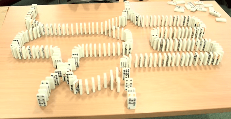
Even though most of us know logic gates like the back of our hands, we just found this awesome explanation video you can use to teach kids in a very fun way — Using nothing but dominoes.
Produced by [Numberphile], our host sets up various “circuits” using dominoes to explain all the various logic gates. Some of the patterns are a bit tricky to setup since you actually have to set up timing based on the spacing of the dominoes — makes us wonder how many bloopers there were!
But don’t take our word for it, it’s well worth a watch after the break.
Still confused? We’ve got a few more examples explaining logic gates including this rather clever use of a chessboard, pulleys, and weights…? No, seriously.
Or what about this unique 2-bit binary adder which uses EL wire to illustrate activate circuits at the System Source Computer Museum just north of Baltimore.
[via Reddit]


A long time ago I think I remember seeing a robot that set up rows of dominoes. It would be pretty sweet to have a robot that sets up elaborate “circuits”
Was this the one you were thinking of?
https://youtu.be/de4xdOVVROQ
interesting, but on the world record that was broken this machine would have had problems. at Manchester they didn’t set up on a massive slabbed floor. I imagine introducing a sheet of paper and a rubber band to tension the domino’s would make this a viable all-surface solution to the tedium of setting up a long chain.
Wasn’t this featured on HAD or am I just thinking of a random reddit moment?
Building an inverter with dominos is easier than you think, just use lever. There no rules that says all dominos must be standing at start. Lay a domino on its long edge instead of its short one. Lay another domino on it flat just off center so that the output end touch table. consider other end, the one standing high as the input. If a trigger domino fall on the input this end will fall to table and the other end will rise. This is an inverter.
Was wondering how he was going to do a NAND gate as then you can build any logic function from them (technically it’s not possible to do the invert/negate feature unless you have an extra input that is always ‘pushed’ but that is likely to confuse his analogy)
Can’t imagine any number of inputs allowing an invert so nand nor and invert etc are not possible at all. You can have a correct output with an extra input but the truth table at the start is not valid.
I saw the big ones on TV a while ago, it was manic.
As I said, it’s possible but it’s really a cheat as we’d always need to push a domino to ensure the output falls (this is effectively an extra input that is always ‘1’).
A few ways to do it but take the XOR and remove the ‘OR’ output (so it now has two outputs and two inputs). If one of the inputs is always pushed, then one output behaves in the opposite way to the remaining input.
If you then remove of the other output (which we don’t care about because it will always be ‘0’), then, tada, you have an inverter.
NAND truth table:
\ _0_ _1_
0 | 1 1
1 | 1 0
So if you tie one of these inputs to 1, you effectively reduce the table to NOT.
Using a dual rail representation for Boolean values makes inversion possible. It also makes it possible to make circuits that aren’t so sensitive to timing. Downside is that the number of dominoes needed is larger:
http://www.srm.org.uk/papers/domino.pdf
You could possibly do inversion by having a ‘clock input’ there… I guess that should do. If there would be a toppling input, it’d just knock the clock feed off, and if there wasn’t, the clock would pass straight through. Yeah, that should dl.
But if you consider sequential logic, you just treat that ‘extra pin’ as the clock input! One-shot, but still plenty to get the idea of sequential vs. combinational logic across.
For anyone who doesn’t know, [Numberphile] is [Brady Haran], who produces a metric fuckton of Youtube science videos on the channels Periodic Videos, Numberphile, Computerphile, Sixty Symbols, and…tens more? Those are the ones I watch.
I wouldn’t say his largest adder is a failure. Just a good demonstration of cross talk and race conditions.
awesome! but it will never be Turing complete…