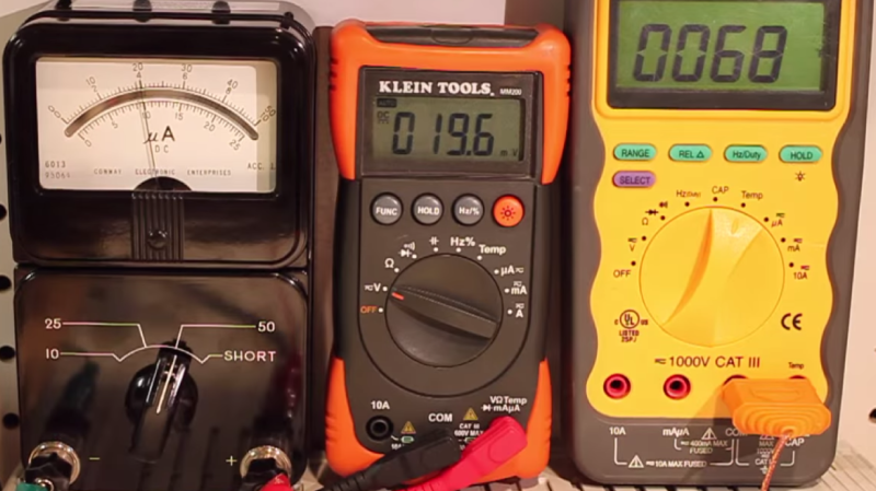
[Craig] sent in this tip about a simple hack he built to convert an old analog micro-ammeter into a thermometer using a few parts. There’s a certain charm to retro analog meters, and there was enough space inside the old meter to accommodate the tiny breadboarded circuit and the three AA batteries to convert it into a cool looking centerpiece which is useful too!
He used the 3-pin MCP9700 analog temperature sensor connected to a LTC1541 – a combined comparator, op-amp and band gap reference voltage all rolled into one package. The thermometer displays 1uA per degree Celsius, has an output of 1mV per degree Celsius for external temperature monitoring / data logging, and draws just about 20uA. While the build itself is pretty simple, [Craig] took the time to walk through every design decision he made in the video after the break. This starts with the design for his circuit, and moves on to the selection of parts and their values. The video is a must-watch for anyone wanting to learn more about precision op-amp based designs.
The three batteries will drain over time, and a circuit like this one requires a stable reference voltage. That is taken care by the bandgap reference voltage from the LTC1541. This eliminates the use of additional voltage regulators, and allows the circuit to work from 4.5V down to about 3.3V. Check the video after the break to listen to [Craig] describe how it works. We’re not sure how quickly it responds to changes in ambient temperature since the sensor is enclosed inside the meter, so maybe some vents at the back, or bringing out the sensor might be a good idea.


“So what’s the temperature today?”
“About… 5 amps”
wait, this is a pure linear circuit? no code? no downloading to it? no clock or crystal?
uhm. I don’t get it.
(lol)
nice job. love the old meter movements, as well.
The fact that this is called “Vintage” makes me feel old.
I know precisely how you feel.
No, no, not “old”, “vintage”.
Very nice.
Excellent explanation of an opamp differential amplifier.
++ for using a bandgsp voltage reference.
Excellent Extrapolation and Definition!
I can not stress the the fact of how cleanly and straightforward this was presented.
May I add an idea to this? Since it was mentioned @around 6:30. Concerning the reference voltage / V1, About the divider resistor “temptation”.
Would a micro voltage joule thief provide the minimum 3.3v until the batteries are completely dead? I don’t know how long the batteries would last pertaining the drain level if common 3 AA are used.
I guess the big deal is how much space is available to integrate a JT, OR even building in a battery recharge that would be isolated if the device is off.
There is an entire subculture regarding building Joule Thief and lighting LEDs. The biggest and only issue I see from them is battery leakage.
@14:00 “10 years is good enough for me”. Forget everything I just said. I don’t think standard Alky batteries can even be stored that well. Damn, I am really impressed though, doing the math and showing and explaining the working. A++
BTW [Craig] the analogzoo com/2015/01/building-the-widlar-hassler/ seems really awesome. If we could pair this with a ESP and connection to Wolfram. That would be epic.
I’ll be the person that hates this hack because it destroys an older piece of equipment that is still useful…
an analog uA meter is useful if you want to see trending, or pulsating values. Something digital readouts suck at. And it’s a uA meter, so it’s very sensitive which makes it useful in a lot of ways.
A tear is shed. – R.I.P.
It uses the meter to display micro-amps, so it’s functional parts are all still necessarily in working order. Perhaps he’s made a hole in the case or something, if he’s lazy. But he hasn’t destroyed it. He’s given it a new life where it’s beauty can be seen in public, doing useful work! A grand retirement for an old measuring tool.
With the right choice of components, it might be possible to make a version of this run indoors off a solar cell. Then it’d be a permanent and lovely thermometer, even better.
You know, I hate to be that guy who feels he has to chime in with a suggestion on something that someone did that works and they’re proud of (and rightfully so)… but I gotta do it.
Instead of 3 batteries, have you considered using a single one and a boost converter to get a regulated supply voltage? It’s a particularly attractive solution in this case because the current draw is so low.
I had a very similar need for my Crazy Clock. Existing solutions taped a pair of AA batteries on the back of the clock so that they could run at 3 volts, but I wanted to re-use the single AA battery holder that was already there. The NCP1402 (though you could also use an NCP1400A since the current is so low) not only allows a single battery to power the system at 3.3 volts, but it also allows the clock to keep running all the way down to around half a volt or so – using up more of the battery before quitting.
SparkFun sells a breakout board for the NCP1402 if you don’t want to do the SMT thing yourself.