Most modern computers are able to dynamically adjust their operating frequency in order to save power when they’re not heavily used and provide instantaneous-seeming response when load increases. You might be surprised to hear that the lowly 8-bit AVR microcontrollers can also switch CPU-speed gears on the fly. In this edition of Embed with Elliot, we’ll dig into the AVR’s underappreciated CPU clock prescaler.
The Fuses
Most (all?) AVR microcontrollers come straight from the factory with their system clock set to run at one eighth of the internal oscillator’s speed. For instance, a stock ATmega168 has an internal RC oscillator ticking away at 8 MHz, but it’s divided down to 1MHz by default. In the bad old days, when dinosaurs roamed the earth and the ATmega8 was the new chip on the block, you had to “burn a fuse” to change this and get the chip up to full speed.
The fuses are configuration bits that stay constant across reboots and aren’t changeable from your code or from within a bootloader — they have to be changed using an external hardware programmer. The idea is that they contain configuration bits that are so sensitive you don’t want something as commonplace as buggy code to mess them up. Things like low-power brownout detection, chip start-up times, lock bits to stop you from reading out the program memory, and so on are stored in the fuse bits.
Basically the fuses contain all the settings that can “brick” your AVR and force you to reach for the high-voltage programmer. Figuring the fuse settings you need is a bit tedious: I’ve always used an online fuse calculator to make sure I get them right.
 Atmel apparently initially thought that CPU clock speed was one of those don’t-touch parameters. Fair enough; we’ll look into what breaks when you change gears below.
But keeping you from changing the clock speed dynamically also removed an important means of reducing the chip’s power consumption. So the newer chips let you control the system clock prescaler from software.
Note that if you’re using an external crystal oscillator, you’ve still got to program the appropriate fuse bits to enable its use. You can’t switch back and forth from an external clock to the internal one from within your code. However once you’ve got the AVR running on an external crystal, you can still use the clock prescaler to change gears (relative to the crystal’s frequency) on the fly. Which is to say, you can change the CPU prescaler on an AVR-based Arduino.
Using The Prescaler
Which chip families have a software-adjustable clock prescaler? All of the ATmegax8 chips (48, 88, 168, and 328) and most of the modern Tinys, from the Tiny2313 to the Tinyx4, x5 and x61 families, support changing the clock multiplier on the fly. There are others as well, and you can sift through the io.h file for your favorite chip to look for CLKPS definitions.
The short version is that your chip will probably have a prescaler unless you’ve got a stash of neolithic ATmega8’s kicking around that you’re trying to finally use up.
The actual sequence for changing the prescaler is deliberately made a little bit complicated: like turning the keys to launch a nuclear missile, it’s not something you want to do by mistake. First, there’s a prescaler-change enable bit that must be set in order to change the clock division bits. But the enable bit gets automatically reset four CPU clock cycles after it’s turned on, so the timing is tight to get the new division bits in. If an interrupt fires in the process, you won’t manage to set the clock speed in time, so you’d better turn off interrupts when changing speeds as well.
Conveniently enough, the GNU AVR libc provides pre-written assembly code that does this dance for you, takes care of differences across chips, and make your code a ton easier to read in the process. Once you include “avr/power.h“, changing the CPU clock is an easy as clock_prescale_set(clock_div_64). Now your chip is running at 125kHz (= 8MHz / 64).
Instead of the old-school fuse-flashing to get your chip running at full speed, just include clock_prescale_set(clock_div_1) somewhere in your initialization routine. Piece of cake.
The Catch(es)
So now you can change all of the CPU clock speed at will from your code. What could possibly go wrong? In short, everything that relies on the system clock for its timing.
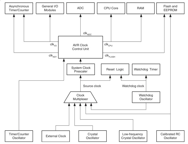 As you can see, most of the AVR’s hardware peripherals use clocks that are derived from the CPU system clock run through the system clock prescaler. The timer/counters, all of the serial I/O (USART, SPI, and I2C), and the analog-to-digital converter (ADC) all have their own sub-clocks that are divided down versions of the system clock.
The good news is that changing any of these to work at your new CPU speed is as easy as re-setting their clock divisors. The simplest solution is to write something like a “switch_to_8MHz()” function that switches the CPU speed and reinitializes the various hardware peripherals at the same time.
The commonly used standard delay functions, _delay_ms() and _delay_us(), are going to be messed up because they rely on a compile-time macro definition, F_CPU, and that can only take one value. If the macro F_CPU is set to 1MHz but then you change the clock speed down to 125kHz, all of your delays are going to be eight times too long when you’re running slow.
The delay problem is a bit tricky because the built-in delay functions only take constants as arguments, so you’ll need to write your own delay routines that take the current CPU speed into account. This could be as easy as simply looping around a fixed delay eight times when you’re running the CPU eight times faster, for instance. Setting a “delay_multiplier” global variable to specify the number of loops and updating it when you change CPU speed is probably the best way to go.
In Conclusion
So you can see that while it’s trivial to change clock speed from your code, a little care is needed to make sure all of the AVR’s peripherals play along. But if you’re looking to save a little power and the sleep modes won’t work for you, changing the gears that divide the system clock is a great way to go. And even if you’re not going to change the CPU speed on the fly, at least you don’t have to burn the fuse bits just to get an AVR chip running at full speed. Give the CPU prescaler a look!


That is why I like newer devices: the clocks have individual prescallers, so you can turn down the CPU without turning down the clock for the peripherals or timers or interface.
However, I cannot think of any case where I needed to switch more than between 32KHz and X MHz clock, basically between running super slow and super fast.
Challenge accepted.
1) You need to do ADC at a slower rate to prevent aliasing.
2) You want to keep wakeup response fairly quick, buy still extend battery life (in between)
3) You want to change to a multiple of a refresh rate.
4) Odd frequency waveform generation when doing DAC.
Regarding #1, wouldn’t running your ADC slower exacerbate any aliasing problems? It would potentially be useful to run an ADC at an intermediate frequency in order to get some power savings without aliasing, but I don’t see how lowering ADC frequency by itself is going to prevent aliasing.
Wakeup from the watchdog timer is fast; 4 clocks if I remember correctly. Sleep mode with the watchdog uses much lower power than dividing the CPU clock.
I am a newb, but I’ve seen a lot of the watchdog, could you elaborate what in the world a dog is doing watching things on a microcontroller?
The watchdog is basically a deadman timer that runs behind everything else the CPU does while executing code. It has the lovely ability to be very low level, effectively one of the last things to die when all else goes wrong. It typically runs in either an interrupt mode where the watchdog timeout will trigger an interrupt routine, or it can run in system reset mode where the watchdog timeout will trigger a jump to reset the chip.
It is special in it’s priority. As an interrupt it operates at a priority similar to external interrupts and above all internal timers, uarts, i2c etc, It is also the only timer based interrupt that can wake an AVR chip from power-down mode, a sleep mode deep enough that all internal and external clocks are stopped and can normally only be awoken externally. As a reset it operates with the highest priority and will reset an AVR regardless of what it is currently doing.
Typically it’s used as a deadman where when your CPU is idle you tell it to reset the watchdog timer as an indication that everything is normal. If you run into a scenario where a bug in your code or some bizarre external circumstance causes your chip to end up in an endless loop or not fall out of an interrupt correctly, the reset code isn’t run, the timer times out, and the entire AVR is forced to reset.
This can be abused in creative ways and is frequently done by things like bootloaders to force an AVR to reset. For instance in some applications I have an external reset button that is multi-purpose (i.e. not the reset pin) where if I hold it down for a few seconds. It executes code that enables the watchdog timer with a really short timeout, and then locks up the CPU by delaying (issuing NOP commands in a loop) until the watchdog resets the chip.
Because coding is quite hard, sometimes a program isn’t perfect, and one thing that can happen is the program getting stuck in an infinite loop, running the same loop over and over because you set the exit conditions wrong. But what if your “infinite” loop is just a really long loop that’s supposed to happen? How do we tell?
So a watchdog timer is a programmable time-out. You send a message to it’s address every so often in your code. This message resets the timer. If for some reason it doesn’t get it’s message, ie your code is stuck, then the timer times out, and the watchdog resets the controller, back to the beginning. The duration of the timer, you can also set in code.
So as you’re writing your code, you make sure to call the watchdog (or “kick” it) every so often. How often depends, obviously, on how long you’ve set the timer to, and how long you approximately think your code’s going to take to run. You scatter “kicks” into the code as necessary.
Then you have the reset routine do something sensible to recover safely. Often, you include code that checks if the watchdog has timed out, so you know why the reset happened. You can log this in your debugging.
If the bug that causes the timeout happens often, you fix the code. But just in case, you have the watchdog for any unforseen circumstances, stuff you can’t predict, so you know your fire-alarm or whatever will never be stuck in a loop. You test all you can for things like this, but as I said, just in case, sometime bugs escape testing.
The watchdog is nice and low-level and is built as the “black box” of the chip, even if something like a voltage wibble upsets your chip, the watchdog should be there, the last part of the chip to go wrong, resetting you back to a known state.
5) You’re generating PWM, and want to run at a constant but reduced clock speed to save power; rather than dynamically changing the clock speed which would require recalculating PWM settings and possibly introduce glitches if not careful.
6) You’re outputting NTSC or VGA signals via SPI, and the simple SPI clock prescaler doesn’t allow you to generate the frequency you need.
I find it strange that the internal RC osc still runs at 8MHz even when the CPU clock is subdivided down. If they just ran the peripheral clocks divided against the RC osc instead of the CPU clock, you could switch speeds without worrying.
Yeah, like I said, newer devices have separate prescalers. Once you selected the 8MHz internal you can run the CPU at a speed and peripherals at another speed.
Devices with PLL may also have nice tricks like running the PLL with an output that is much higher then maximum CPU clock, but that clock can be used for peripherals.
They might be lazy not wanting to have internal signals crossing many clock domains – each time you do that you have to synchronize the signals adding delays and complexity. They might even run everything at the 8MHz and only use the divider output for driving the enable inputs of their flops in their logic.
For what it’s worth, avr-libc provides a convenient way to specify fuses in your C code. For an example, see here: https://github.com/arachnidlabs/minishift/blob/master/firmware/slave/main.c#L10
Very cool. I’ve never seen that before.
Does that preamble turn into something that’s directly flashable with AVRDUDE? Can I script this in from a Makefile? Or it is just for record-keeping purposes?
(And I’m not bagging on record-keeping: I usually include a text file with the AVRDUDE fuse command documentation purposes when I do anything funny with the fuses.)
NVM. Just went through your Makefile. :)
For folks reading along: the GCC compiler spits out the right fuse bit values, you can trim them off into their own files, and then use those files to burn in the right fuses automagically. Very slick.
I fear this method. Forcing me to get the datasheet out and look at the fuse registers means I’ve *VERY* careful when buring fuses. This means I don’t have to get out a recovery clock or high voltage programming becuase of accidentally writing the wrong fuse values. I’m sure someone will tell me that using library #define constants is better than doing it by hand, but I believe I think harder about it when doing it manually.
I tried using it about a year ago and found it is not well supported. I found bugs in the fuse definitions, and I also ran into problems getting it to work with avrdude.
I also think configuration like fuses should not be in your code; meep them in the Makefiles. I do wish there was more consistency in fuse bits across the different AVRs.
If one is dividing the CPU frequency by a set amount, wouldn’t it be the same to write delays in the code to be divided by the same amount? For instance, if I have clocked the CPU down by 8 (8MHZ / 8), and I have an original delay of 500ms on a PWM pin, it theorizes that I sohould divide my PWM pin by the same factor to get the correct delay on the pin (i.e.; 500ms / 8 = 62.5ms).
No.
I don’t know all the AVR chips, but other micro lines have peripherals that operate in parallel with the CPU, so your software delays don’t affect their timing.
Actually, I think that should be a qualified yes.
It’s possible [Irish] is generating software PWM in the most primitive way, by looping enough times to consume 500ms, toggling a pin, and repeating. In which case the number of times he’d loop would have to be reduced if he slows down the CPU.
And if he’s using hardware PWM, while the peripherals run in parallel with the CPU, their clock is *usually* derived from the CPU clock. So their timing settings would have to be reduced as well if affected.
It’s a “yes” with the mega AVRs. All the peripherals I mentioned are sub-divided off of the CPU clock after the CPU clock prescaler takes effect. I verified this with an oscilloscope and a mega168, just to be double-sure. (I suppose it could be different for different AVR chips — wouldn’t be the first time.)
I agree that it would be cool if they all ran off the internal RC osc directly instead.
If you’re doing PWM using the hardware peripheral, and if your CPU clock is running 8X faster, all else equal, you’ll need to count up 8X as high to get the same elapsed wall-clock time.
Alternatively, you may be able to change the timer/counter’s prescaler to slow the counter back down to where it was. This would be my first choice if it works, because you won’t have to worry about non-integer counts when you divide down, for instance.
Either way, though, you’ve got to tweak something.
Don’t forget this for the mega328 and similar:
” The Asynchronous Timer clock allows the Asynchronous Timer/Counter to be clocked directly
from an external clock or an external 32 kHz clock crystal. The dedicated clock domain allows
using this Timer/Counter as a real-time counter even when the device is in sleep mode.”
If you do the delays by looking at the timer powered from dedicated clock source, you will not care about CPU scaling.
I don’t see this being used much to dynamically change speed with processing, but it could be useful to turn the clock way down while polling or waiting for interrupts.
I’m confused.
Why would one poll or wait for interrupts using a spin loop at all? Isn’t that what sleep mode is for?
Can you cite a use case where polling is better than sleep mode – in systems that need ultra low power?
I kinda dodged this in the article, because I hadn’t pulled out the microammeter and tested it myself, but it’s the concensus on AVR Freaks that it’s just about a wash between running faster and sleeping more vs running slower. So the first-order answer to your question is that you could do it either way, power-wise.
Of course, you might also be able to both underclock and use sleep modes for even lower consumption. Power minimization with AVR’s is at least a few more column’s worth of tricks, and I use idle and power-down modes whenever I can.
But still assuming there’s some performance demand, why underclock? This is the use-case you wanted: Fastest possible response to infrequent external event.
Coming out of sleep takes some time. If you’re on the RC osc, and at the default fuse settings, it actually waits a bit more than 65ms(!) coming out of power-down mode for the clock to re-stabilize. This delay is configurable with fuses, but the datasheet recommends waiting it out if you need the RC osc to be stable.
There’s also standby mode, which keeps the osc running but turns off the CPU. This comes up in 6 cycles, but you need to be using an external crystal.
Then there’s interrupt-routine setup time, which adds a few more cycles.
All this adds up, and depending on your particular application, you might get faster response by polling with the CPU clocked-down. You _certainly_ will in the case that you’re waiting 65ms for the RC osc to settle down.
Yeah – changing clock speed doesn’t save much power at all – to do some unit of work takes the same number of clocks, and it’s each of the clock transitions that use power.
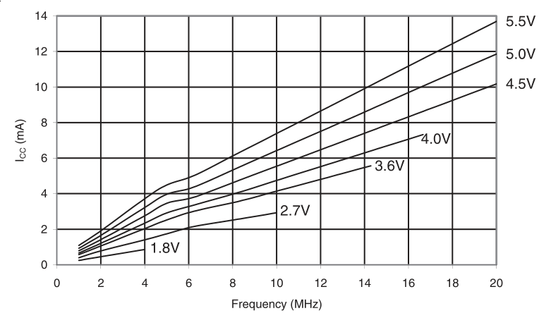
The thing that *does* save power is running at a lower voltage. So normally you would want a chip to drop the clock, and then also drop the supply (or conversely raise the supply voltage, and then the clock). Running at a lower clock rate normally allows operation at a lower voltage, as per the datasheet chart in the article where a drop of 1v saves 3mA of Ioc.
So unless you can dynamically control the supply voltage too, it’s probably best to run as fast as possible and to then go into the deepest permissible idle state as you say.
If you are not doing anything most of the time and only need speed in short bursts (ie waiting on input at 1Mhz then pulsing a pin at 16Mhz once a command is received)
In my case there isn’t a way to get an interrupt pin to wake me up when I receive input so I must remain running rather than asleep. Also having a wakeup timer probably isn’t an option either since I don’t really know when I will recieve the input and I must react quickly. It would be very cool to design a circuit to automatically switch the voltage output of a TL873 though.
Overall you are correct though the biggest return is running the avr at 4.1v for 16Mhz instead of 5v. It would be really nice if I could run at 3.3v at 1Mhz though. I was able to achieve some power savings running at 8 or 16Mhz and doubling my baud rate on the serial port when at 8Mhz however all my timings were off due to millis() being hardcoded.
This is mainly a problem for me as I have many 200+ devices powered with a TL873 each running from a single rail…. so I want to use as little idle power as possible.
Not sure what the TL837 is… Is it a typo?
In any case, it is easy to change the output of an adjustable regulator (linear or switch mode). You can put a resistor in parallel of the voltage divider on the feedback path that is controlled by a MOSFET from a GPIO.
Similarly, a mux can be used to switch clock external source. I did that back in high school usng a 74HC00 and using 2 of the gates in the mux itself as crystal oscillators. :P
Is it worth the silliness for a 8-bitter when you could use ARM chips that has all of these and more and price competitively?
A Typo yes I was refering to the TL783 … not sure what the point of switching the clock externally would be… it would still mess timing in the code.
Also, I don’t really need the design complexities of a 32bit chip at least in my use case…. its good enough and I just want to reduce power usage because it is pretty low hanging fruit. The TL873 is already a wash vs a SMPS since I can already low the voltage more grandularly vs the SMPS which has a fixed voltage output even thought it is more efficient at providing that output.
All this talk about shifting the voltage while running… has anyone actually done this? Is it something that’s within-specs? Does it need to be a gradual shift, or can it be instantaneous? Seems like the sorta thing that would mess with output/input voltages of internal gates that it’d be a bit risky… All those decoupling-caps are put on ICs for a reason.
Nice tutorial, [Elliot]!
A few months back I tried a new PIC variety, and it had a such a complex combination of prescalers and PLLs that for the life of me, I couldn’t figure out how to get the core running at exactly the max rated speed using the internal RC oscillator. It was not a simple and exact small integer multiple, like in prior cases. And the datasheet provided no sample settings.
I tried working out some combos by hand, but each was foiled by exceeding the upper or lower frequency limits of individual modules in the chain.
What I ended up doing is writing a short program that exhaustively searched every possible setting combo. Those that exceeded any limit were discarded, and of the valid possibilities it kept the closest one. Took a few minutes to write the program, another few minutes for it to run. When done it provided valid settings that got me within a few hz of the target. There’s a divide by 83 in there if I recall right, LOL.
I mention this because it might be useful should anyone else find themselves in a similar predicament.
Ah. I call this the Far.Q algorithm. There is the need for one in almost every datasheet.
Definition: Far.Q Algorithm –
1) – would have been so so easy to include in the datasheet
2) – always seems to have an infinite number of variables at first glance.
3) – is not calculable with traditional maths techniques.
4) – requires programming techniques that are not otherwise used anywhere.
5) – often requires initial program to write a second program in a different language.
6) – the logical analysis gains an extra dimension with each evaluation.
7) – programming solution always requires recursive functions and recursive class constructors.
8) – programming sessions include several iterations of verbalising the algorithms name – Far.Q
Love it! Most of those applied here, almost #8 too.
Great idea.
I hear where you’re coming from with more complex chips. I’ve been playing with the STM32F4’s, and their clock tree is more like a small forest! (That said, you have immense flexibility.)
Is 83 prime? I think you get extra points for that.
Yep, 83’s prime.
Haven’t played with the STM32F series. Freescale ARM clock selection is a mess. There is a whole RPG quest type of adventure – collecting magical items and go to places not related just to change clock option on the fly. i.e. You have to go through states or certain clock sources even though you don’t even want them just to get at the one you really want. Almost hopeless to figure it on your own from datasheet if it is your first time.
I find the PICs very versatile in this respect.
“You can’t switch back and forth from an external clock to the internal one from within your code.”
PICs can.
The number of registers you need to deal with depends on how many clock sources and options your PIC has. There’s basically just two for the type of options mentioned in this article.
You can even set some configuration bits to be ‘default x – further define and change on the fly in software’.
One thing to note is that there’s not a linear relationship between clock speed and power consumption. Just because you’re clock is less than 32kHz, you probably aren’t using less power.
I wish I knew enough about the internals of the PICs to have written about them too.
But re: linear relationship power vs clock speed. I haven’t verified this with a microammeter (and I probably should!) but in the datasheet, the graphs are pretty linear across the whole range and really linear-linear below 1MHz.
Taken from ATmega48P/88P/168P datasheet, p. 370 for instance: http://imgur.com/KLuh3sw
On a chip I’m working on (Atmel) there’s the special oscillator that runs basically by itself (32kHz) in sleep mode (sub 20uA current); I don’t know how that works. What sucks is something simple like the given delay function turns on another 32kHz clock and wakes up out of sleep mode; apparently Atmel thought we wouldn’t need a working delay function (pfft…). I heard but haven’t seen it myself yet that PIC’s generally give out delay functions that work in sleep mode, maybe it’s a fluke since I’m basing on 1 chip. Freescale had an even simpler one-liner one (of course you have to go digging to find where it really is).
I had to make an annoying “delay function” that’d run in sleep mode, works good but it doesn’t feel right. Definitely encourage trying hooking up an ammeter and watching it waking up and going to sleep or doing other stuff though, interesting.
A trick to get long, low-power sleeps is to use the watchdog timer which runs on an independent low-freq (128kHz for the megax8 series) clock. It’s a little more hassle than waking up by interrupt, but with a little timer trickery, you can have the chip in deep sleep and only woken up every 8s, using very very little power when idle.
But yeah, a lot of more featureful chips have a separate 32kHz-ish real time clock timer running alongside. It’s actually super handy.
Dynamic power in a CMOS device (ignoring static leakages etc) is P = alpha C V^2 f .
https://en.wikipedia.org/wiki/CMOS
Running at low clock speed means you can reduce the voltage which let you further reduce power.
Yep – dropping the clock speed alone is just making things slower.
It’s not that only the PICs can, many micros can. it’s just that you are probably comparing a newer PIC with an older AVR.
As micros get more and more advanced, more and more of the fuse settings become software configurable and you can change everything you want on the fly.
Bogdan – nah. On the whole, old/new big/small PIC are more versatile in this respect than even new AVRs. The 16f883 is a good example of an older (same vintage) sub $2 part. It’s all over the first page of the datasheet. It has a dedicated separate ultra low power 32kHz oscillator that can be used to do housekeeping or wake it from sleep. Anytime you switch clocks there’s a definite risk the crystal fails. PIC have tech to prevent a complete lockup.
…Although in recent years others (not AVR) have gotten just as good if not better with this stuff.
tekkieneet – “..ignoring static leakages..”
Not a big deal but….
I wouldn’t go around and depend on files like io.h for figuring out what my chosen chip is capable. Not too long ago, I wrote my own set of definitions for a chip because the ones found in the *.h files for my model were wrong.
The old definitions worked, but they crippled a number of the more useful features that made me select the chip in the first place. Yet no one else noticed. Can’t figure why. I submitted the changes and they were folded in on the next update.
I discovered them because I actually looked the datasheets for that chip. Which is what everyone should do. Use the .h file as a supplement but not outright replacement of your understanding of the hardware… unless there is no datasheet then you really have no choice eh?
True enough. I’m still surprised that the tiny2313 is on the list. Maybe I should have dug one out to check.
The way the AVR datasheet is written, particularly in the I2C section, I wasn’t sure if the I2C peripheral was tapping the internal RC oscillator before or after the prescaler. So I did you one better and didn’t trust the datasheet _or_ the defines, and verified behavior with code and an oscilloscope. (At least on a mega168.)
Of course nothing beats the actual hardware and testing for the behaviour. That’s why errata exists. My point was, one shouldn’t be using the .h files as the sole source of information about a chip, especially during this Arduino era where you have a crap ton of software only guys with only the most cursory understanding of the underlying hardware writing the code.
Not saying ALL developers should know exactly how their Intel 64 bit computers work with such intimacy, but when you’re looking at the AVR and PIC 8 bit line, it wouldn’t be unreasonable.
Are these still called configuration “fuses” on FLASH? In the days of OTP chips they were called “fuses” but after in the introduction of EPROM, EEPROM and FLASH, I thought they were called configuration “bits” on such chips????
“fuse” makes me think of one time programmable (OTP).
Atmel calls ’em “fuses”. I just roll with it.
To be fair, they’re special config bits — not modifiable except through external programming or treachery. And you also set them by writing a zero and clear them with a one, unlike every other normal bit in the binary universe.
So maybe it is a good idea to use an archaic name just to remind you that they’re different?
From memory the change occurred with the transition from the PIC16C84 (OTP) to the PIC16F84 (FLASH). The 16C84 had been around for a while (and was popular) when the FLASH version was introduced.
The configuration bits were inverted between the two versions as it is normal for FLASH for ‘0’ to be programmed or ‘set’ and ‘1’ to be cleared or unset. An erased FLASH chip is 0xFF FF FF FF … (or 1111111…). You can write ‘0’s over ‘1’s but not the other way around so you can set individual bits if they are ‘1’ to start with.
16C84 was EE, not OTP
Was I thinking of the 18C57 or 16C57 then ???? A while back so my memory is a bit flaky.
Awesome article. Does anyone know if I can run a AVR chip which is rated upto 10MHz by using a 16MHz crystal and prescale the clock by 2? Does the internal CMOS crystal oscillator also have the speed limit?
To be specific, I’m using the ATMEGA88V at 2.7V which only goes upto 4MHz but I have a 8MHz SMD crystal (passive SMD crystals of <8MHz are hard to find).
In my experience with ATmega’s (running at the full 5 Volts) the limiting factor is usually the internal crystal oscillator and I would expect this to be especially so for lower voltages.
The uC core (CPU etc) will run at much higher than rated frequencies. For example a ATmega328P-pu is rated to run up to 20 MHz but it will run fine at 30 MHz. The problem is that the internal crystal oscillator is not so reliable so you need to use an external active oscillator block to run it at much higher than rated clock speed.
The above however may not be the case for lower VCC voltages. You may find that the core wont overclock so much with 3v3 as it will with 5v0 even if you use an external active oscillator.
Also there are two modes for the internal crystal oscillator and only one will work best at higher frequencies if you try to use the internal oscillator at all.
Thanks Rob. I was under the impression that the internal CPU setup/hold times would not be met at the higher speed/lower voltages. Didn’t suspect the crystal oscillator.
Rob, it can run, but it is no guarantee. The manufacturer takes some margin so that even the worst devices run at a guaranteed frequency, which is why you will find some surpass the limits by a high margin.
People on the internet will tell you that it runs overclocked, but so far I have yet to see any significant tests(high number of devices, a way to tell ic CPU works correctly etc).
If you want faster, grab a faster device.
Agreed on the article’s awesomeness, and useful comments to boot.
Vikas: I can’t vouch for being within specs, but I can say that I’ve driven an AVR rated for 16MHz off a 32MHz crystal *oscillator*/clock and the AVR’s internal divide-by-two…
OTOH, I can also vouch for having used an AVR rated for 8MHz at 5V at 20MHz at 3.6V.
If it’s not for a product, I’d say just experiment :)
Ok, I’m going to praise the article for it’s nice writing and interesting topic.
I’m going to criticise it for it’s bad design choice: You’re a designer, in 2015, and you need to chose a low-power MCU. You still use an AVR. Why? There’s sufficiently powerful MCUs out there that can easily run with a fraction of the power.
For example, take the TI MSP430 MSP432P401; at 24MHz (!), it uses a maximum(!) of 4.6mA. If used in low-power active mode, it uses less than 0.1mA, whilst still being around as fast as the Atmega at a similar speed.
To be honest, the Atmega family has come to a certain degree of obsolence. Though still being excellent chips with a nice community, its silicon design is somewhat outdated. People that want easy development and lots of libraries simply use ARM Cortex Msomethings, and people who need low power the MSP430 series. They never were cheap, so people don’t use them where 10000-piece cost matters.
Take the TI TM4C123FH6PM, which is on the TIVA C launchpad, an ARM Cortex M4F. Yes, that’s a 32 bit microcontroller. Yes, it has a floating point unit. Yes, it can go up to 80MHz easily. Yes, the TI standard library doesn’t pass the software quality standards I’d have for an afternoon project. It might use a lot more than the Atmega in full power mode, running at 80MHz (http://www.ti.com/lit/ds/symlink/tm4c123fh6pm.pdf p. 1361), 35mA (unless you constantly loop through flash memory), but then again, it’s running at full 80 MHz, and does a lot more FlOp/s than the Atmega, so you can just put it to sleep sooner, where it only uses 3mA or so. Not even mentioning deep sleep. Also, the ARM architecture makes it really easy to switch between the power modes quickly, so that’s not really “impossible” for power-conscious projects.
Of course, that’s kind of the biggest ARM in that series, and it includes a lot of peripherals. One might simply go for a different series, for example the ST LP0 family of low-power ARMs, and whoosh, they promise you 87µA/MHz, so just to compare a 32bit RAM-rich ARM with an old 8bitty AVR at the same clock: at 16MHz, that ARM would use 1.4mA…
I hope you understand why I can’t really justify making an article about power-efficient AVR design. It’s not going to happen, for technological reasons — the silicon base is just too old.
LOL TL;DR: “you shoulda used a 555″/”why aren’t you using a RaspPi?” –irrelevent?
I highly doubt this article is in any way for real designers. It tells of a concept that is simple and known. Like you say, there are better devices out there so there is no point in discussing about these old ones for products.
They are however the most popular microcontroller for hobby which is why it makes sense.
Real designer can read datasheet, so unlikely they would *want* or need an article from a 3rd party. Heck even the tech support of a certain vendor tell me not to trust their software tool over the datasheet.
ARM chips have crazy power saving modes. For ultra low power, they lower the core voltage just enough to run at a few MHz. Even with the MHz hands tied behind their back, their powerful peripherals with DMA support means that the CPU is not busy polling or servicing interrupts both can take a bit of CPU cycles in a 8 bitter.
Thanks for both the praise and the criticism!
The spirit of the article was much more “so you’ve got this processor spinning its wheels and using up too much juice, how can you fix it?” than a clean-slate low-power design tutorial.
I also cry a little every time I see an Arduino running 16MHz on a linear regulator plugged into a 12V wall wart sitting in CPU-spin delays. At least it’ll keep the house warm, right?
But seriously, a lot of the projects we feature aren’t compute intensive and are bashed out in a Saturday afternon on whatever processor is at hand or familiar. For a bunch of our readers, that’s an AVR / AVR-based Arduino. Rather than go processor-spec-shopping, it’s more important to get the thing done. I was just suggesting a quick-and-dirty way to drop the power usage without changing much more than a bit of code.
But yeah, that’s a bass-ackwards design process. :)
Hi Elliot,
thanks for the excellent reply!
I do agree, for existing projects, this is an extremely helpful post; also, for basically everyone who has had a project that for example wasn’t really practical because it drained the battery too fast.
So what I personally take from this post is: being reminded. Being reminded of the fact that whatever MCU I use, it probably has some reduced clock, sleep, or low voltage modes that I can use to the benefit of my project!
The article also points people to the fact that when they use an ATMega in a design of their own, and they don’t need to drive loads from the MCU power supply itself, they can get away with quite a few mA less than the maximum spec says — making it possible to, for example, use a small solar panel and a supercap to let that project basically run forever, under certain climate assumptions!
So all in all, I feel my criticism was a bit harsh; I might have gotten to much speed when talking about alternatives to the AVRs.
Yeah but on the other hand, standing by itself…. the Arduinos. Certainly the chip with the best community support ever. Lots of small and medium-sized companies supporting it. And as much as anything, it does the job. It’s power requirements and everything else are good enough for what people use them for.
Fortunately the weeno chaps abstracted enough that versions of it run on ARM more or less seemlessly. So there’s no dead-end. Quite possibly the weenos will move on to ARM in the middle future. But the simplicity of 8-bits is itself valuable, when people want to take little steps past the weeno environment, and do a bit of hardware messing. From there you can understand the whole chip, and you’ve taken a very useful step, hopefully with the minimum of pain. It’s a simple 8-bitter where the hardware is what you talk to, no operating systems (though I know ARM can do the same), low-level it’s just what it seems.
They’re still making the PIC 16 series after gods know how many years, with the RISC ones just extending the range. They have their purpose. Simplicity is just one of them. The outdated BASIC Stamp lasted for ages too. Though that said, powerful and cheap ARMs have only become so widespread in so many configurations in the last few years, who knows what’s coming?