Hackaday Prize Entry: Recording RC Planes With Third Person View

With the latest advancements in small, cheap video transmitters, it’s no surprise First Person View remote-controlled aircraft are so popular. It’s the easiest way to get into a cockpit without having to spend thousands of dollars and fifty or so hours on a pilot’s license. Despite all the technical challenges of FPV flying, there’s still one underserved part of recording RC aircraft: third person view, or as it’s more commonly called, ‘handing a camcorder to your friend.’

[Walker Eric] would like to do something about that. He’s always wanted nice videos of him flying his plane, and he can’t film and fly at the same time. He can build a robot, though, and that’s his entry for The Hackaday Prize.

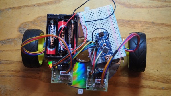
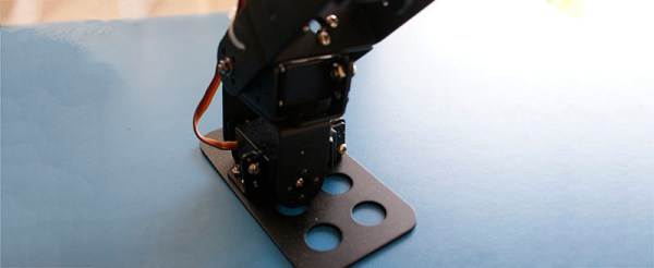
[Walker]’s project uses a base station with a camcorder mounted on a gimbal. The electronics for this setup are surprisingly simple – just a GPS beacon transmitting telemetry down to the base station. By comparing this data to a GPS receiver on the ground station, the direction of the plane can be computed.

There are a few problems with this setup. Altitude measurement with GPS isn’t very accurate, so [Walker] is using a pressure sensor as an altimeter on the GPS beacon. The current setup works great, and is a fantastic improvement over the OpenCV setup [Walker] tested out before moving to GPS.

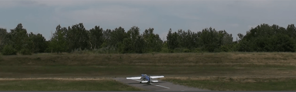
[Walker] already has some incredible video of him flying some planes and quads around his local field shot with this system. You can check those out below.


The 2015 Hackaday Prize is sponsored by:

Continue reading “Hackaday Prize Entry: Recording RC Planes With Third Person View”

A Real Dash For A Truck Simulator

[Leon] plays Euro Truck Simulator 2, and like any good simulator, there are people out there building consoles, cockpits, and dashboards. In [Leon]’s case, he wanted a dashboard for his virtual trucks and cobbled one together out of a dash taken from a VW Polo.

This project was inspired by [Silas Parker] and his Arduino-based dashboard made out of a cardboard box, some servos, and a few LEDs. It worked, but [Leon] realized just about every dashboard made in the last decade or so has a CAN bus. You can just buy a CAN bus shield for an Arduino, and a dashboard can be easily found at any junkyard.

Right now, [Leon] is in the process of finding the CAN bus addresses of the relavent dials and LEDs on the dashboard. He found the tachometer at 0x280, and a bunch of indicator lights can be found at 0x470. Combined with a standard computer steering wheel and the telemetry SDK for Euro Truck Simulator 2, [Leon] has the beginnings of a virtual big rig on his desk.

Cheap, Easy To Build Robot For Beginners

Robotics kits are a great way to get folks , young and old, interested in hacking and learning the basics. Quite often, the cost puts them off – it’s no fun if you mess things up while learning how to put an expensive kit together. Many kits are too polished and that leads to beginners feeling that they’ll never be able to build something complex like a robot. The Shonkbot is what the team at Bristol Hackspace came up with for a robot that is obvious in its working and encouragingly easy to build, even for kids (with supervision).  To that effect, they completely avoided custom PCBs and laser cut bits. The Shonkbot is built from easily available parts and some commonly available materials. They aimed to build it for £5, but managed £15. With proper planning and time, they guess it can be brought down to £10.

The Shonkbot is built using an Arduino Nano, two stepper motors with their drivers, a 3xAA battery box and some bits and bobs. Assembly takes about an hour for a 10-year-old and then they can reprogram it in another workshop or at home. The “frame” of the Shonkbot is an old CD-ROM or DVD disk. Everything is hot glued to this frame. At the centre of the disk, a Sharpie is inserted and the Arduino code then allows the robot to draw on paper. Upgrades include adding an IR LED, a photo transistor and a buzzer to allow the Shonkbot to detect objects, or communicate with other Shonkbots. Build instructions are detailed in this document, and the code is available from the Github repository. Here is a photo album from their first build workshop which was held recently.

Thanks to [Matthew Venn] from the Bristol Hackspace for sending in this tip. Check the robot in action in the video below.

Continue reading “Cheap, Easy To Build Robot For Beginners”

Tracking Bitcoin With The ESP8266

[Kendrick] was looking for something to do with an ESP8266 WiFi module, and since he loves Bitcoin and Arduino, the obvious solution was to make a Bitcoin price tracker.

The ESP8266 is a complete microcontroller with a WiFi chip and a few pins for a serial connection. It’s certainly possible to write some firmware for the ESP to get the current conversion rate of Bitcoin, but for simplicity’s sake, [Kendrick] chose to use an Arduino for this project. He’s using a 5V Arduino, and the ESP operates on 3.3V logic, but a few Zeners take care of the logic level conversion.

The code running on the Arduino checks the CoinDesk API minute, parses the JSON coming from the API, and prints the current Bitcoin price to the serial port. For tracking the current conversion rate of Bitcoin, it’s vastly overkill. This project could have a few interesting applications, from hooking up a few seven-segment displays, to an RGB LED mood lamp that keeps track of this magic Internet money.

Walk Your Pet Robot

Anyone who’s ever tried to build a bipedal robot will quickly start pulling their own hair out. There are usually a lot of servos involved, and controlling them all in a cohesive way is frustrating to say the least. [Mark] had this problem while trying to get his robot to dance, and to solve it he built a control system for a simple bipedal robot that helps solve this problem.

[Mark]’s robot has six servo motors per leg, for a total of 12 degrees of freedom. Commands are sent to the robot with an RC radio, and the control board that he built, called the Smart Servo Controller, receives the signals and controls the servos appropriately. There are 14 outputs for servos, operating at 12 bits and 50 Hz each, as well as 8 input channels. The servo controller can be programmed on a computer with user-selectable curves for various behaviors for each of the servos on the project. This eliminates the need to write cumbersome programs for simple robot movements, and it looks like it does a pretty good job!

Full disclosure: [Mark] currently has this project up on Kickstarter, but it is a unique take on complex robot control that could help out in a lot of different ways. Since you don’t need to code anything, it could lower the entry barrier for this type of project, possibly opening it up to kids or school projects. Beyond that, even veterans of these types of projects could benefit by not having to do as much brute-force work to get their creations up and moving around!

Continue reading “Walk Your Pet Robot”

Embed With Elliot: Shifting Gears With AVR Microcontrollers

Most modern computers are able to dynamically adjust their operating frequency in order to save power when they’re not heavily used and provide instantaneous-seeming response when load increases. You might be surprised to hear that the lowly 8-bit AVR microcontrollers can also switch CPU-speed gears on the fly. In this edition of Embed with Elliot, we’ll dig into the AVR’s underappreciated CPU clock prescaler.

Continue reading “Embed With Elliot: Shifting Gears With AVR Microcontrollers”

Neopixel Ring Compass Takes Things In A New Direction

A couple of years ago, [philo mech] came across [David Ratliff]’s NeoPixel compass project. Ever since then, he’s wanted to make his own. To his delight, [philo mech] was able to find time to do just that.

An Arduino Pro Mini drives an LSM303DLHC compass/accelerometer breakout board and a 12-LED NeoPixel ring. The heading is indicated with a red ‘Pixel between two yellow ones.  In the video after the break, [philo mech] gives several demonstrations of the ring’s red indicator in relation to a standard compass arrow.

This colorful compass currently boasts two very useful modes: one to track the whereabouts of North, and the other for determining the user’s current heading. Mk. II  will compensate for tilt and will employ a 16-Pixel ring to display finer degrees of directional change. Want to make your own? The code is pasted in the video’s comments.

Continue reading “Neopixel Ring Compass Takes Things In A New Direction”